Balanced Input/Output Assembly Guide
We no longer stock these kits but you can order the PCBs directly from OSHPark here:
Thank you for purchasing a Building Block kit. The Building Block kits were designed to be easy to use, but they do require some electronics knowledge (or a willingness to learn) to implement successfully. Since the possibilities for use are endless, this guide will focus on providing you with the basic information you need to research and design your own project.

Schematic and Circuit Description
The Building Block 1 & 2 circuits do little more than carry audio and power to and from the ICs (U1), which do account for most of the circuits' performance.
Balanced Input Circuit

The network composed of C1-C3 filters out noise above the audio spectrum. C4 blocks any DC from being passed to the next stage; it's relatively large value (100uF) ensures that it will not create a filter in the audio range with the input impedance of the next stage. If you prefer not to have the electrolytic capacitor the signal path, you may replace it with a jumper at your own risk. CB1 and CB2 perform the important "housekeeping" task of power-supply bypassing. These capacitors reduce noise and provide small amounts of local storage for supply current. U1 is a dedicated balanced line receiver chip. Any of the pin-compatible offerings from THAT Corporation, Texas Instruments, or Analog Devices may be used. The THAT 12xx series of chips boast the best specs and have been widely adopted in the pro-audio world.
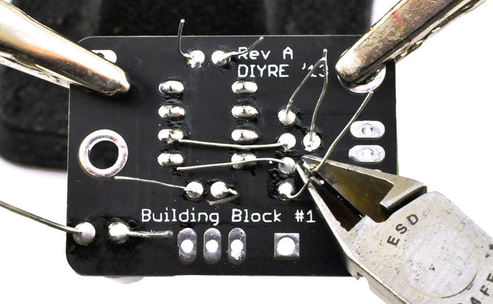
Note: The + and - inputs for the Balanced Input PCB Rev A are marked backwards. To maintain the correct polarity of your signal, you should connect the positive input to the pad marked "-" and negative input to the pad marked "+". We apologize for the inconvenience. This mistake was corrected with Rev B.
Balanced Output Circuit

As in the Balanced Input circuit, CB1-CB2 provide local power-supply bypassing and C1 blocks potentially harmful DC from entering the circuit. The capacitors C3 and C4 prevent DC offset at the output of the circuit. The inductance of ferrite beads F1-F2 react with the capacitance of C5-C6 to shunt RFI noise to the chassis, away from the audio circuit. U1 is a balanced line driver IC. The THAT Corp. 1646, TI DRV134, and SSM2142 are all pin-compatible.
IC Choices
(Click a part number to see pricing and availability.)
Balanced Input ICs
| Manufacturer | Part # | Gain | Comments |
|---|---|---|---|
| THAT | 1240P08-U | 0dB | Conventional line receiver |
| THAT | 1243P08-U | ±3dB | Conventional line receiver |
| THAT | 1246P08-U | ±6dB | Conventional line receiver |
| THAT | 1200P08-U | 0dB | High CMRR |
| THAT | 1203P08-U | ±3dB | High CMRR |
| THAT | 1206P08-U | ±6dB | High CMRR |
| THAT | 1250P08-U | 0dB | Low cost |
| THAT | 1253P08-U | ±3dB | Low cost |
| THAT | 1256P08-U | ±6dB | Low cost |
| Texas Instruments | INA134PA | 0dB | Conventional line receiver |
| Texas Instruments | INA137PA | ±6dB | Conventional line receiver |
| Analog Devices | SSM2141PZ | 0dB | Conventional line receiver |
Balanced Output ICs
| Manufacturer | Part # | Gain | Comments |
|---|---|---|---|
| THAT | 1646P08-U | +6dB | |
| Texas Instruments | DRV134PA | +6dB | |
| Analog Devices | SSM2142PZ | +6dB |
Bill of Materials
Balanced Input
| Qty | Part # | Value | Type |
|---|---|---|---|
| 1 | U1 | Balanced line receiver | THAT 12xx, TI INA13x, SSM2141 |
| 2 | C1, C2 | 470pF | Ceramic or film, non-polarized |
| 1 | C3 | 47pF | Ceramic or film, non-polarized |
| 1 | C4 | 100uF | Electrolytic, non-polarized |
| 2 | CB1, CB2 | .1uF | Ceramic, non-polarized |
Balanced Output
| Qty | Part # | Value | Type |
|---|---|---|---|
| 1 | U1 | Balanced line driver | THAT 1646, TI DRV134, SSM2142 |
| 1 | C1 | 100uF | Electrolytic, non-polarized |
| 1 | C3, C4 | 10uF | Electrolytic, non-polarized |
| 2 | C5, C6 | 100pF | Ceramic or film, non-polarized |
| 2 | CB1, CB2 | .1uF | Ceramic, non-polarized |
| 2 | L1, L2 | Ferrite bead |
Assembly


Connecting to the Outside World
Once the PCBs are populated and tested, they are ready to be wired up to the "outside world." Each PCB contains three sets of pads for connecting the Building Block to other circuit blocks.
Balanced Input
- The audio input should be a balanced, professional (+4dBu), line-level audio signal. You can use a 3-pin XLR or TRS 1/4" jack.
- Hot (+) goes to XLR pin 2 or TRS "Tip"
- Chassis goes to XLR pin 1 or TRS "Sleeve." Pin 1/Sleeve of the jack should also be connected to the physical chassis.
- Cold (-) goes to XLR pin 3 or TRS "Ring"
- The audio output should be connected to the input of an unbalanced circuit, or a TS (2-pin) TRS jack.
- + goes to the next circuit's audio input or TS "Tip"
- Ground (unlabeled on PCB) goes to the next circuit's audio ground or TS "sleeve"
Balanced Output
- The audio input should be an unbalanced, professional (+4dBu), line-level audio signal. You can wire the balanced output directly after an unbalanced circuit, or to a TS (2-pin) 1/4" jack.
- + goes to the source device's audio output or TS "Tip"
- Ground (unlabeled on PCB) goes to the source's audio ground or TS "sleeve"
- The audio output can be connected to a 3-pin XLR or TRS 1/4" jack.
- Hot (+) goes to XLR pin 2 or TRS "Tip"
- Chassis goes to XLR pin 1 or TRS "Sleeve." Pin 1/Sleeve of the jack should also be connected to the physical chassis.
- Cold (-) goes to XLR pin 3 or TRS "Ring"
Power
For both units, power inputs must be connected to positive and negative voltage rails and the power supply ground. The power rails must be a DC voltage within the range of +/-4 to +/-18vDC. Your power supply must be a dual supply that generates both positive and negative voltage rails; these will typically be specified with a +/- as in "+/-12vDC" instead of simply "12vDC."
Each PCB can be expected to draw between 2-20mA of supply current. If you are in doubt regarding power supply voltage or current, check the datasheets for your chosen ICs. The proper connections are:
- + goes to the positive power supply output
- 0v goes to the power supply ground
- - goes to the negative power supply output