Colour Palette Rev E (mkII) Assembly Guide
Damaged or Missing Parts All kits and parts are checked before being shipped to you. If something arrives damaged or if your kit is missing a part, please open a support ticket to inquire about a replacement. Missing parts will be replaced at our expense. Damaged parts should be returned for verification. If the part shows signs of use beyond what was necessary to determine that it was damaged, DIY Recording Equipment, LLC reserves the right not to replace the part.
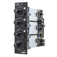
Thank you for purchasing a Colour 500-Series Palette mkII!
If this is your first DIY project ever, we recommend reading our Getting Started Guide.

Required Tools
You'll need the tools below to complete this build.

Soldering Iron
We recommend an adjustable-temperature station, such as the $40 Weller WLC100.

Solder
You can use 60/40 "leaded" solder or lead-free. We recommend 60/40 because it flows better and is easier for beginners to use.
Phillips Head Screwdriver
A #1 Phillips head screwdriver.
Wire Cutters
You'll need a pair of good "snips" for cutting of the excess leads after soldering.
Optional Tools
These tools aren't strictly necessary but can make your build a bit easier.

Multi-Meter
If you find the color bands on resistors a bit hard to read, you can use a meter to sort them with absolute confidence.
Desoldering Pump
If you accidentally solder something in the wrong place, a desoldering pump can save the day.
0. Resistor Calculator
Type in the value of the resistor you need and this tool will show you the corresponding color code.
Resistors

Sort Bag 1
Print the Print the Palette mkII Component Sorting Sheet (PDF) and sort the resistors. You can identify the resistors by their color code or with a multi-meter.

Bend and Place Resistors
Bend the resistor leads at the body and then insert them into their respective places on the PCB.

Bend Resistors Against PCB
Bend the leads of the resistors against the bottom of the PCB so that the resistors stay in place during soldering.
Solder Resistors
Now solder the resistors to the PCB. Observe good soldering technique: heat the pad and lead for 2-3 seconds, apply a small bit of solder, and continue to heat the pad for another 2-3 seconds. Allow each solder joint 10 seconds to cool before moving on to the next one. The finished joints should be shiny and should have just enough solder to cover the pad entirely.

Trim Resistors
Once all of the solder joints have cooled, use your clippers to trim away the excess leads. Your goal should be to clip as close as possible to the joint without clipping the joint itself.
Small Capacitors, Fuses


Solder CB1-CB8
As you did with the resistors, place, bend, solder, and trim the small capacitors.
FAQ: Are these parts polarized? Nope, insert them any way you like.
Solder Fuses
Insert the fuses F1 and F2 just up to where the leads begin to kink. Then solder and trim.
Sockets, Diode Bridges

Sort Bag 3

Place IC Sockets
Place the four 8-pin IC sockets in the U1-U4 positions on the PCB. Make sure to align the notch in the sockets' plastic with that one the PCB.

Bend and Solder IC Sockets
Use a flat-head screwdriver to bend two leads of each socket against the PCB. Then solder the sockets. There's no need to trim the excess leads.

Place Colour Sockets on Bottom of PCB
Flip the PCB over and place the 8-pin Colour sockets in the CON4-CON6 positions. Make sure you have placed the sockets on the bottom side of the PCB. This is the most common error in the entire build!
When you are positive that the sockets are on the bottom of the PCB, solder one leg of each socket to hold them in place, then flip the PCB over and solder all of the joints.

Place Diode Bridge
Place and solder the 4-pin, integrated diode bridge in the BR1 position. Make sure to align the design on the diod bridge's body with that on the PCB silk screen.
Large Capacitors

Sort Bag 4

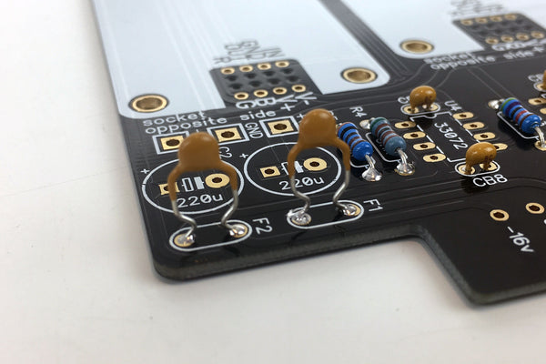
Populate Large Capacitors
Note that these caps are polarized, meaning they must be inserted in the PCB in a certain direction. The longer lead is the positive terminal, while the strip on the body corresponds to the negative terminal. Place the capacitors on the PCB, taking extra care to place the longer lead closer to the "+" marking on the PCB. All of the capacitors should face the same direction.
Once you've double checked their orientation, bend, solder, and trim the caps.
Pots, Daughter Board Hardware

Sort Bag 5

Place Mounting Brackets
Flip the PCB over and insert the brackets from the bottom of the PCB. Solder them, but do not trim the leads.

Place Potentiometers
Place the potentiometers in positions VR1-VR4. Bend two leads of each pot against the PCB, then solder and trim.

Place Daughterboard (DB) Sockets
Place the sockets in the CON1A and CON2A positions. Bend some leads to hold them in place, then solder and trim.

Insert Headers and Standoff
Insert the 12-pin headers loosely into the sockets. Also loosely thread the standoff into the hole between the two sockets. There's an extra screw in bag 6 in case you drop one.
LEDs, Switches

Sort Bag 6

Populate R4
Place, solder, and trim R4 on the DB.

Place DB Brackets
Place the remaining brackets through the top of the DB and solder.

Place Switches
Place the switches in SW1-SW4 positions. Bend two leads of each to hold them in place. Then solder them and trim the leads.

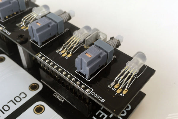
Attach DB
Place the DB over the headers CON1B and CON2B and screw it to the standoff. Press the headers up so that the black, plastic square-posts are flush with the bottom of the DB. Then solder the headers to the top of the DB.

Place LEDs
Place the three LEDs in the LED1-LED3 positions. Place the longest leads of each LED through the holes marked "-". Double check the orientation of the LEDs before moving on.
Hold the LEDs upright and press them down so that their leads rest against the top of the motherboard. Now bend the LEDs forward towards where the front panel will be.
Hold LEDs in Place
Solder just one lead of each LED from the top of the DB to hold them in place.

Solder LEDs from Bottom
Remove the DB, flip the PCB over, solder the LEDs, and trim their leads. Then place the DB back on the MB and screw it down.

Attach Front Panel
Using the included hex wrench, screw the front panel onto the PCB assembly via the four mounting brackets.
Integrated Circuits

Sort Bag 7
Pay close attention while sorting and placing the ICs. There are three different types, which need to go in the right places for the Palette to work.
Note that kits now include a DRV134 instead of THAT 1646 for U2.

Place ICs
Place the ICs in their respective sockets. You may need to bend their leads inward a bit for them to sit nicely. The ICs will have a notch or circle to indicate pin 1. Align the notch or circle with the notch on the PCB and sockets.
Front Panel Hardware

Sort Bag 8

Fasten Lenses, Caps, and Nuts
Press the LED lenses through the holes in the front panel, press the caps onto the switches, and fasten washers and nuts over the pots.

Attach Knobs
Turn all of the pot shafts to the 12 o'clock position (10 detents from full CW or CCW). Now place the knob over the shaft so that the white indicator line points to the middle of the top position. Then fasten the knob with the included hex wrench; note that there are two set screws per knob.
Final Checks
Before you wrap up, check the following things:
-
Capacitor orientation: Is the stripe on the cap on the opposite side from the "+" marking on the PCB?
-
IC orientation: Does the dot/notch on the IC align with the notches on the socket and PCB?
-
Resistors: Do all of the resistor positions correspond the chart and/or sorting sheet?
-
Soldering: Is every solder joint shiny and clean? If one is cloudy or misshapen, try reheating it for 8 seconds and adding a tiny bit more solder.
-
Trimming: Are all of the excess leads trimmed down as close to the joint as possible?
All good? Congrats on finishing your build! Have a question or problem? Drop us a line.
Help Us Improve
1
2
3
4
5
6
7
8
9
10