LINE2AMP RevC v3 Assembly Guide
If you purchased your kit before 11/1/2013, please see the RevC v2 Assembly Guide.Safety Precautions, Warranty, and Disclaimer Improper soldering and handling of electricity can cause serious injury and damage to your property. Read and understand the instructions below before beginning your project. Follow the instructions, build carefully, and use the appropriate tools. Build at your own risk. DIY Recording Equipment, LLC is not responsible for any damage or injury resulting from the assembly or use of your LINE2AMP kit. You are the manufacturer of your LINE2AMP. It is your responsibility to turn this group of parts into a working piece of recording equipment. DIY Recording Equipment, LLC does not guarantee the success of your project and disclaims any Implied Warranty of Merchantability. Please visit the support forum for assembly support.
Damaged or Missing Parts All kits and parts are checked before being shipped to you. If something arrives damaged or if your kit is missing a part, please open a support ticket to inquire about a replacement. Missing parts will be replaced at our expense. Damaged parts should be returned for verification. If the part shows signs of use beyond what was necessary to determine that it was damaged, DIY Recording Equipment, LLC reserves the right not to replace the part.
Damaged or Missing Parts All kits and parts are checked before being shipped to you. If something arrives damaged or if your kit is missing a part, please open a support ticket to inquire about a replacement. Missing parts will be replaced at our expense. Damaged parts should be returned for verification. If the part shows signs of use beyond what was necessary to determine that it was damaged, DIY Recording Equipment, LLC reserves the right not to replace the part.

Required Tools
It's possible to complete the LINE2AMP with only three hand tools and a spool of solder. If this is your first DIY project, please see the Getting Started Page for beginner tips and recommended tools.

Optional Tools
A multi-meter and desoldering tool are essential for troubleshooting and replacing faulty or misplaced components. A "helping hands" tool is great for magnifying and stabilizing your work surface.
Transformer Testing
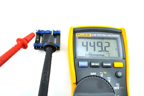
Test the transformer before you begin soldering. Pin 1 of the transformer is indicated by a notch in the blue plastic; the pin numbers increase clockwise with the pins facing upward.
Set your meter to read resistance and perform the following measurements:Probe pins 1 and 3 with your multi-meter leads. The resistance should be about 434Ω.
If you do not get a reading, make sure your meter's threshold is set to at least 2kΩ.Probe pins 5 and 7. The resistance should be in the region of 114Ω.

1
Identify the resistors, bend their leads, and insert them in the PCB. Resistors are identified by the electronic color code (Wikipedia)
. 1kΩ, R3

2
Insert the transformer into the PCB, matching Pin 1 (indicated by a notch on the blue plastic of the transformer) to the square pad on the PCB. Turn over the PCB and solder the resistors and transformer pins, be careful to heat each pin for no longer than 5-8 seconds while soldering. Alternate between components and rows of transformer pins to allow time for each joint to cool down.

3
Once the joints have cooled, trim the leads as close as possible to the joint without touching the joints themselves

4
Locate the pre-trimmed and stripped pieces of hookup wire included with your kit. Remove the small lengths of excess coating and tin the exposed bare wire by applying a small amount of solder.
5
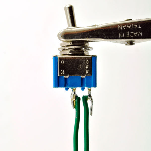
Insert two of the green lengths of wire into the lugs of the ground-lift switch with their tinned tips facing outward as shown. Solder the wires to the switch, heating each lug for no longer than five seconds to avoid overheating the plastic.

6
Solder lengths of green, red, and black wire to the pins of the input jack as shown. Green corresponds to the sleeve/ground pin, red to the tip/signal "hot" pin, and black to the ring/signal "cold" pin. Note that the sleeve/ground pin is indicated by a 45 degree angle on the corner of the jack body.Depending on parts availability, your kit may come with 5-pin "switching" TRS jacks. In this case, simply ignore the two pins adjacent to the sleeve/ground pin and solder to the three pins shown in the picture.

7
Solder the remaining lengths of wire to the output jack. Red corresponds to the tip/signal pin and black to the sleeve/ground pin.

8
Solder the jacks and switch to the PCB and trim the exposed leads. The pads are labeled "T," "R," and "S" for the tip, ring, and sleeve pins of the input jack and "T" and "S" for the pins of the output jack. This switch wires may be soldered to either pad.

9
If you have a multi-meter, it's a good idea to test the completed circuit before installing it in the case. Set your meter to read resistance with a range of at least 2k and place the probes on the tip and ring pins of the input jack (orientation does not matter). Your meter should read between 430Ω and 450Ω.Increase the resistance range to 20k and place the probes on the pins of the output jack. The resistance should be close to 15kΩ. If either of these test readings are not correct, please post your problem at the Support Forum.

10
Insert the black screws through the top of the case and screw on the aluminum standoffs with your fingers. Leave the standoffs loose for the moment to make installing the PCB in the next step easier.
Note: If you purchased your kit after September, 2014, you kit will include shorter screws that do not protrude through the standoffs.

11
Place the PCB on the standoffs, making sure the jacks and switches are facing the appropriate holes. Then thread the lock nuts onto the screws with your fingers and tighten the screws with a screw driver. Finally, insert the jacks and switch into their respective holes and fasten them.
Note: If you purchased your kit after 9/14, fasten the PCB to the standoffs with the four remaining 1/4" black screws.

Fin
Congratulations on completing your LINE2AMP! Now go abuse some guitar amps. If your LINE2AMP is not working, please open a Support Ticket.