Colour Palette Rev A (mkI) Assembly Guide

Table of Contents
Print out the handy Component Sorting PDF and put all of the parts in the kit in their respective places on the printout. Now your components are identified, organized, and ready to be stuffed into the PCB. Time to fire up the soldering iron!
Jargon Definition: PCB = Printed Circuit Board. The copper-and-fiberglass board that all of the components are soldered to.
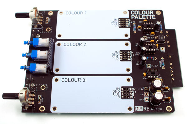
Populating the Motherboard PCB

Place the sockets for U1-U3 (don't instert the ICs themselves yet) and BR1 in their respective places on the PCB, indicated by the white outlines and part numbers. Make sure to align the notches in the IC sockets with the corresponding notches in the outline on the PCB. Tape the components to the top of the PCB with your low-tack tape, flip the board over, and solder the leads.
Jargon Definition: IC = Integrated Circuit, also known as a "chip."

Insert resistors R1-R4 into the PCB. To secure them to the PCB before soldering, hold the resistor bodies flush against the board with one hand while bending the leads against the other side of the board with the other hand. Now flip the board over and solder away.
Soldering Tip: It's a good practice to wait 30 seconds between soldering different leads on the same component. This let's the solder to cool completely so that wiggling the component doesn't compromise the joint. An easy way to implement this practice is to solder one lead of each resistor first, wait a few seconds, and then solder the remaining leads in the same order.


Place the ceramic capacitors CB1-CB6 and C4 in their places near the IC sockets. Be careful not to mix up the bypass capacitors, which are marked "104" and C4 which is marked "22J." Bend the leads against the bottom of the PCB, solder, and trim the leads as you did with the resistors.
FAQ: Are these capacitors polarized? Nope. Some capacitors are polarized and must be oriented one way or another to work correctly. These aren't those kind. If there's any "correct" way to orient the ceramic caps, it's with the side with the markings pointed outward from the IC sockets so they can be easily checked.

Capacitors C3, C5, C6, C7 and fuses F1, F2 are roughly the same height and are not polarized. Install them in their respective places in any direction you please, then bend, flip, solder, and trim.
Capacitors C1 and C2 are polarized components--installing them in the wrong direction will "let the smoke out." Thankfully, the caps' polarity is well marked both on the PCB and the capacitors themselves.
Positive:- Square pad and "+" marking on PCB, longer lead and no marking on cap
Negative:
- Round pad and no marking on PCB, shorter lead and gold band with "-" markings on cap
Got it? Now insert C1, C2 PCB, bend, flip, solder, and trim.


Next, place the switches in their positions on the board and install the front panel. Be sure to screw in both of the front panel mounting screws completely so that the board and panel are in the correct position. Set the switches so that all completely are in the "out" position. Once you're satisfied that the switches are aligned correctly, tape them to the board, flip, solder, and trim.
Note: The first round of kits included two pairs of front panel screws: one with a hex socket and one with a Phillips head. We recommend using the Phillips head screws because the head sits flush with the front panel, while the socket screws protrude slightly.
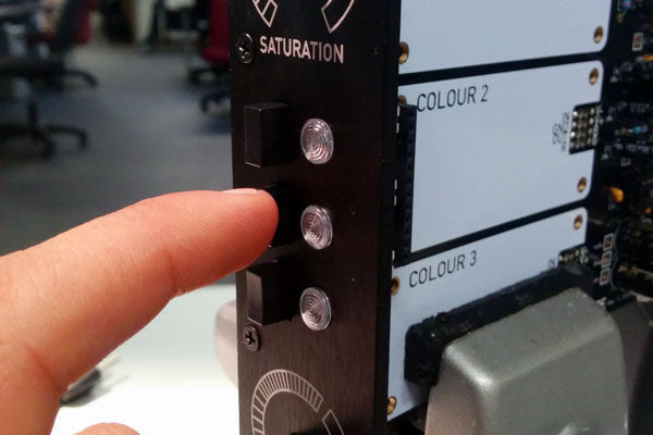
Finally, remove the tape and test the switches with the front panel. Voila! Take a moment to appreciate the smooth motion of the switches clicking easily in and out.

The final components to install on the motherboard are the pots VR1 and VR2 (VR = Variable Resistor). Solder the three electrical pins as well as the two legs of the mounting bracket to the PCB. If you think you may someday replace these pots with the stepped saturation/trim sets, do not solder the mounting brackets to the board.
If you opted for stepped controls, see the Stepped Control Add-On Assembly Guide for this section.
Assembling the LED Board
As with the socket, installing the header CON2 upright is usually a tricky task that's made simple by a couple clever "hacks."
Push the long pins of the header into the socket part way, leaving about 1/8" of the pins exposed. Now locate two of of the motherboard ICs that we haven't installed yet. These make an ideal platform for the LED PCB when set on top of the two outer switches.


You've probably noticed that there are no holes in the pads for the LEDs. Because the LED leads will sit parallel to the board, it will be easier to solder them right to the surface of the board. Again, this will involve some clever steps to get everything mounted correctly, but the soldering itself is actually easier than the through-hole stuff you're probably used to.
Begin by "tinning" the LED pads by heating them and applying a small amount of solder directly to the pad.
 \
\
Now we'll position the LEDs and PCB for soldering. First, if you haven't already, press the LED lenses through the front panel (you may have to press hard!) and put the white washers over the back of the lenses.
Second, press the LED PCB into the socket on the motherboard.
Third, snap the LEDs into the lenses and orient them so that the longest lead (the cathode) of each LED corresponds to the offset pad and "-" on the PCB legend.
Finally, pull the LED PCB up from the motherboard slightly so that it presses up against the leads of the LEDs. It's better to pull the PCB up a little too high than to have it sit too low. The idea here is that the leads should want to push down into the pads rather than wanting to pull up from them.

Soldering the leads to the PCB requires a two-handed technique: one hand holes the leads in place with pliers while the other heats the pad and lead with the soldering iron. Once the joint becomes hot, the existing solder will melt and bind with the lead. Remove the iron but continue to hold the lead in place with pliers until the joint cools completely. It shouldn't be necessary to add any solder beyond what we left on the pad during tinning.
Repeat the process for each lead and pad and then trim the excess leads at the edge of the pads.
Finally, press the LED PCB back down toward the motherboard so that the black square posts are flush with the socket.
Great job! You've completely populated your Colour Palette.
Testing and Final Touches

Now that we've soldered and trimmed every component, it's a good practice to clean the bottom of the board with isopropyl alcohol and a lint-free cloth. The humble q-tip cotton swab is a good substitute for a lint-free cloth; just make sure to pick up any lint left behind.

Before inserting the ICs in to the sockets, it's a good idea to do one final check to make sure there are no major problems with the power rails. Connect your Palette to a power source. For most users without a dedicated bench power supply, this will be your 500-series rack. If your rack is of the horizontal-mounting type, such as the A-Designs 500HR or Chamelon Labs CPS-501, you can remove the top panel of your rack to perform this test. If you rack is of the vertical-mounting type, such as the API Lunchbox or 500VPR, you may be able to perform this test by inserting the Palette into the left-most slot of the rack and turning the rack on its side.
Turn on the power and perform the "smoke test." That is, carefully watch and sniff for smoke while the unit is powered up. If you see or smell smoke, power down your rack immediately, remove the Palette, and contact us or do your own troubleshooting.
Once your Palette has passed the smoke test, perform the power test with your multi-meter. Set the meter to read at least 20 volts DC. Place the black probe on the square test pad labeled "Gnd" and the red probe on the pad labeled "+16v." The meter should measure about 16vDC. Now move the red probe over to the "-16v" pad, keeping the black probe on "Gnd." The meter should read -16vDC. If either of these measurements are more than one volt off, power down the Palette and do not connect the ICs.

Once your Palette has passed the smoke and power tests, it's safe to install the ICs into their respective sockets. Take note that the ICs do not progress in numerical order from the top to the bottom of the PCB; rather, they go U2, U3, U1. Take care to match the notches in the ICs to the notches in the sockets as indicated in the illustration above.
Check the markings on the IC bodies to make sure you're inserting them in the correct sockets.
U1 = 1246 or 1256
U2 = 2068D
U3 = 1646

Congratuations on competing your Colour Palette!
For tips and instructions on using your completed Colour, please visit the Operation Manual.
Having trouble with your build? Open a support ticket and we'll work through the problem with you.