Colour Stepped Controls Add-On Assembly Guide
The Stepped Controls Add-On Set allows you to convert the Colour Palette's Saturation and Trim controls to 11-position, stepped controls. Each set includes circuit boards (PCBs), switches, resistors, and hardware for two controls. Since the two PCBs are identical, all of the steps below apply to both kits except where noted. The only difference between them is that we'll install them in the Palette in opposite directions.
1. Identify and Sort Resistors
Both PCBs employ the same 10 resistors. Identify them by testing their resistance with a mutli-meter or with the resistor color code.
R1: 33R
R2: 100R
R3: 220R
R4: 390R
R5: 620R
R6: 910R
R7: 1.2k
R8: 1.6k
R9: 2.2k
R10: 2.7k
R2: 100R
R3: 220R
R4: 390R
R5: 620R
R6: 910R
R7: 1.2k
R8: 1.6k
R9: 2.2k
R10: 2.7k

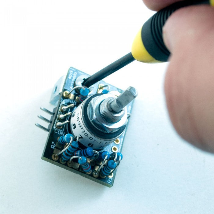
2. Install Switch
Insert the Grayhill switch so that position 1 indicated on the sticker aligns with position 1 on the PCB legend. Do this the same for both Saturation and Trim controls. Solder the switch pins to the PCB; there's no need to trim the pins.

3. Insert Resistors
Insert the resistors into their respective places on the PCB. Because of of the limited space on the PCBs, we will install the resistors vertically so that their bodies are roughly perpendicular to the PCB. Bend one of each resistor's leads at the body so that both leads are facing the same direction.Alternate the orientation of resistors next to each other so that if they do touch their leads will not short against each other. As you insert each resistor, bend the protruding leads against the bottom of the PCB to keep it in place.

4. Solder and Trim Resistors
Turn the PCB over for soldering. Solder one lead of each resistor first, then go back and solder the remaining leads. This will keep you from compromising a solder joint by jostling a resistor while the solder is still wet. Once you have soldered all of the resistors and allowed the final joint to cool, trim the excess leads town to the top of the solder joints.

5. Install 3-pin Header
Insert the 3-pin headers from the bottom of the PCB so that the long, straight pins point out from the top of the PCB. Insert one of the headers in the three holes marked "CON" next to R1; this will be the Saturation control. Insert the other header into the "CON" holes between R7 and R8; this will be the Trim control.Lay the header and PCB on your work surface so that the straight pins of the header stick up and the PCB rests on top of the black square-posts. Solder and trim the headers from the top of the PCB.
6. Fasten to Palette
Now fasten the switch assemblies to your Colour Palette with the small L-bracket and screws. Although the difference is hard to see, one of the legs of the L-bracket is shorter than the other. The longer leg is identified by a thin, scored line on the inside face. Screw in the brackets with the longer leg touching the Palette and the shorter leg touching the switch PCB.
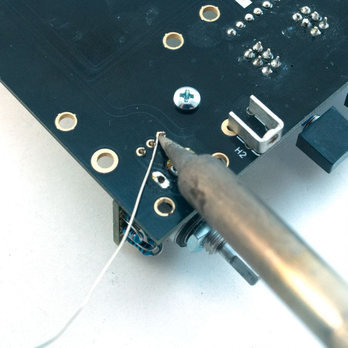
7. Solder Header to Palette
Once you've firmly tightened the mounting screws, solder the headers to the Palette and trim the leads.

8. Install Front Panel and Knobs
Remove the nuts and lock washers from the switches but leave the rubber washer. Install the front panel and then put the nuts and lock washers back on the exposed bushings of the switches. Finally, attach the knobs. Place the shaft reducers inside the knobs and turn the set screws slightly to keep the reducers in place. You may need to apply some pressure to pop the shaft reducers all the way into the knobs. Install the knobs on the switch shafts so that the set screw aligns with the flat area on the Saturation switch and the small circle on the Trim shaft.
Complete!
Great job, your Stepped Control Add-Ons are complete! If you hit a snag during assembly, contact us and we'll help you sort it out: