L2P Assembly Guide
Damaged or Missing Parts All kits and parts are checked before being shipped to you. If something arrives damaged or if your kit is missing a part, please open a support ticket to inquire about a replacement. Missing parts will be replaced at our expense. Damaged parts should be returned for verification. If the part shows signs of use beyond what was necessary to determine that it was damaged, DIY Recording Equipment, LLC reserves the right not to replace the part.
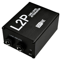
Thank you for purchasing a L2P Passive Line Attenuator Kit!
If this is your first DIY project ever, we recommend reading our Getting Started Guide.

Required Tools
You'll need the tools below to complete this build.

Soldering Iron
We recommend an adjustable-temperature station, such as the $40 Weller WLC100.

Solder
You can use 60/40 "leaded" solder or lead-free. We recommend 60/40 because it flows better and is easier for beginners to use.
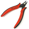
Wire Cutters
You'll need a pair of good "snips" for cutting of the excess leads after soldering.
Optional Tools
These tools aren't strictly necessary but can make your build a bit easier.

Multi-Meter
If you find the color bands on resistors a bit hard to read, you can use a meter to sort them with absolute confidence.
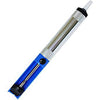
Desoldering Pump
If you accidentally solder something in the wrong place, a desoldering pump can save the day.
Assembling the L2P

Idenfity Parts
Take a moment to identify all the parts of the kit:
- L2P Case
- Foam Pad
- L2P PCB
- Front and back panels
- Input 1/4" jacks (2x)
- Output XLR jacks (2x)
- Toggle switch
- 2.7k resistors (6x)
- 150 resistors (2x)
- Case screws (9x)
- XLR screws (4x)

Sort and Bend Resistors
Idenfity the two 150R resistors and six 2.7k resistors. Bend their leads near the body before inserting them into the PCB.

Place Resistors
Place the resistors according to the values marked on the PCB.
Notes: Since resistors don't have any polarity, it doesn't matter which way the leads are facing. And, since this resistor will not be letting off significant heat, you can place the body flush against the PCB.

Bend Resistors Against PCB
Before soldering, bend the resistor leads agains the bottom of the pcb.

Solder Resistors
Solder the resistor to the PCB. Here are a couple good soldering practices to observe:
- Heat the pad and lead together for 2-3 seconds before applying solder
- Apply just enough solder to cover the entirety of the pad, so that no gold is showing through
- Leave the iron in place while you are adding solder and for 1-2 seconds after
- The entire soldering process should take 5-8 seconds
- Allow the solder joint to cool for about 20 seconds before soldering another lead of the same component

Place Input Jacks
Remove the nuts and washers from the 1/4" input jacks. Then place them in the areas labeled "J1 / INPUT 1" and "J2 / INPUT 2." To keep the jacks in place, bend the leads back with a small flat-head screwdriver as shown.

Solder Input Jacks
Solder the leads of the input jacks, leaving about 10 seconds between each joint.

Place & Solder XLR Jacks
Place the XLRs jack in the "J3 / OUTPUT 1" and "J4/ OUTPUT 2" positions on the PCB. Lay the jacks on their backs with the PCB lying on top of them to solder.
Solder the three metal pins of the XLR jack. Don't solder the two plastic mounting pins.

Place & Solder Switch
Place the switch in the "DPDT" position, and bend the longer leads to keep it in place. Before soldering, attach the front panel via the input jacks' mounting nuts and washers.
Once the front panel is mounted firmly, solder the switch to the PCB.

Trim Excess Leads
Trim away the excess pins and leads with a wire cutter. Cut each lead as close to the solder joint as possible, without compromising the joints themselves.

Slide Assembly into Case
Slide the assembled PCB into the lower channel in the chassis. The front panel should be on the side of the case nearest the "L" in "L2P."

Screw on Panels
Screw in the eight remaining mounting screws. Since these screws are cutting their own threads in the aluminum, you'll feel a healthy amount of resistance the first time you put them in.
It's a good idea to install all four screws on one panel loosely before tightening each one.

Apply Foam Pad
Remove the backing and apply the neoprene foam to the bottom of the case.
Using the L2P

Operation
The L2P (Line to Preamp) is a two-channel, line-level, balanced attenuator. It has two primary applications in the studio:
- Place it after colored mic preamps set on the -10 setting to drive the preamps harder without clipping converters
- Place it between line outputs and and mic inputs on the -30 setting to add preamp color to tracks during mixing

Input
The L2P accepts two balanced inputs via 1/4" TRS jacks 1 and 2. The toggle switch sets both pads to either -10dB or -30dB.

Output
The padded signals exit the L2P via two 3-pin XLR jacks. You can patch the padded signal to any balanced piece of gear, including converters, mixing desks, mic preamps, and signal processors.
Final Checks
Before you wrap up, check the following things:
-
Resistors: Do all of the resistor positions correspond the chart and/or sorting sheet?
-
Soldering: Is every solder joint shiny and clean? If one is cloudy or misshapen, try reheating it for 8 seconds and adding a tiny bit more solder.
-
Trimming: Are all of the excess leads trimmed down as close to the joint as possible?
All good? Congrats on finishing your build! Have a question or problem? Drop us a line.
Help Us Improve
1
2
3
4
5
6
7
8
9
10