SAFE Assembly Guide
Damaged or Missing Parts All kits and parts are checked before being shipped to you. If something arrives damaged or if your kit is missing a part, please open a support ticket to inquire about a replacement. Missing parts will be replaced at our expense. Damaged parts should be returned for verification. If the part shows signs of use beyond what was necessary to determine that it was damaged, DIY Recording Equipment, LLC reserves the right not to replace the part.

Thank you for purchasing a !
If this is your first DIY project ever, we recommend reading our Getting Started Guide.

Required Tools
You'll need the tools below to complete this build.

Soldering Iron
We recommend an adjustable-temperature station, such as the $40 Weller WLC100.

Solder
You can use 60/40 "leaded" solder or lead-free. We recommend 60/40 because it flows better and is easier for beginners to use.
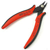
Wire Cutters
You'll need a pair of good "snips" for cutting of the excess leads after soldering.
Optional Tools
These tools aren't strictly necessary but can make your build a bit easier.

Wire Strippers
Removing the insulation from wires with regular wire cutters can be a fiddly, frustrating job. But dedicated wire strippers make it a breeze.

Multi-Meter
If you find the color bands on resistors a bit hard to read, you can use a meter to sort them with absolute confidence.
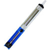
Desoldering Pump
If you accidentally solder something in the wrong place, a desoldering pump can save the day.

Unpack the Kit
Your kit should contain:
- SAFE PCB
- Potentiometer
- Jack
- 2x Diodes (orange and yellow things)
- Resistor (blue thing)
- Capacitor (yellow thing)
- Red Probe
- Black Probe
- Red Wire
- Black Wire
Place Diodes and Resistor

Bend Diodes and Resistor
Bend the leads of the diodes about 1/8" away from the body so they'll be easy to insert into the PCB. Bend the resistor's leads right at the body.

Place the Small Parts
Insert the diodes into the spaces marked "D1-D4." Diodes will only conduct in one direction, so make sure that the lines on the diodes line up with the corresponding lines on the PCB.
Insert the resistor into the space marked "R1." The resistor doesn't care which direction it's placed in.
Insert the capacitor into the space marked "C1." It cares even less than the resistor.

Bend Leads Against the PCB
Before flipping the PCB over to solder, bend the leads against the bottom of the PCB to hold the components in place.

Solder the Diodes and Resistor
Heat each pad and lead for 2-3 seconds, apply a small bit of solder, and continue to heat the pad for another 2-3 seconds. Allow each solder joint 10 seconds to cool before moving on to the next one. The finished joints should be shiny and should have just enough solder to cover the pad entirely.

Trim the Excess Leads
Use your wire cutters to trim the leads down as close as possible to the solder joints.
Place Larger Parts

Place the Potentiometer (Pot) and Jack
Place the pot and jack in the spaces "VR1" and "J2."

Bend the Jack's Leads
Bend a couple of the leads of the jack against the PCB so it'll stay in place. You may need to use the blunt end of the wire cutters to push the leads against the PCB.

Solder the Pot and Jack
Solder the pot and jack to the PCB, including the pot's mounting tabs.

Strip the Hookup Wires
Cut the insulation around the hookup wires about 1/4" from each end. Leave the excess pieces of insulation on the wire for now. If you're careful you can do this with wire cutters, but it's much easier with a dedicated wire stripper.

Twist the Insulation Off the Wires
Twist the extra pieces of insulation as you slowly pull them off the wires. This will twist the individual strands into a nice spiral and prevent fraying during soldering.

Place the Wires
Insert the wires into the holes marked "J1" from the top. Put the red wire in the hole next to the "+" sign.

Solder the Wires
Solder the wires to the PCB and trim them down to the solder joint.
Assemble Probes

Take Apart the Probes
Carefully pull apart the two pieces of the probes. You should be able to remove the plastic backs from the probes without pulling too hard—don't twist the probes, just pull straight back.

Put the Plastic Pieces on the Wires
Put the wires through the plastic-only pieces of the probes as shown.

Insert the Wires Into the Probes
Place the ends of the wires through the holes in the metal part of each probe. Bend the bare parts of the wire against the metal of the probe to create a solid mechanical connection before soldering.

Solder and Trim Wires
Solder the wires to the metal parts of the probes and trim any extra wire.

Put the Probes Together
Put the parts of the probes back together. Press the plastic metal part into the plastic part just enough so that it stays together. You should be able to easily engage the spring to push the hook out from the top of the probe.
Final Checks
Before you wrap up, check the following things:
-
Soldering: Is every solder joint shiny and clean? If one is cloudy or misshapen, try reheating it for 8 seconds and adding a tiny bit more solder.
-
Trimming: Are all of the excess leads trimmed down as close to the joint as possible?
All good? Congrats on finishing your build! Have a question or problem? Drop us a line.
Help Us Improve
1
2
3
4
5
6
7
8
9
10