SB2 Assembly Guide
Damaged or Missing Parts All kits and parts are checked before being shipped to you. If something arrives damaged or if your kit is missing a part, please open a support ticket to inquire about a replacement. Missing parts will be replaced at our expense. Damaged parts should be returned for verification. If the part shows signs of use beyond what was necessary to determine that it was damaged, DIY Recording Equipment, LLC reserves the right not to replace the part.
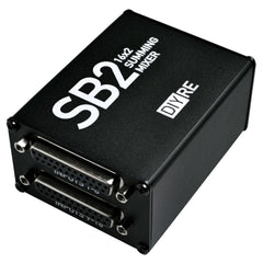
Thank you for purchasing a SB2 Passive Summing Mixer Kit!
If this is your first DIY project ever, we recommend reading our Getting Started Guide.

Required Tools
You'll need the tools below to complete this build.

Soldering Iron
We recommend an adjustable-temperature station, such as the $40 Weller WLC100.

Solder
You can use 60/40 "leaded" solder or lead-free. We recommend 60/40 because it flows better and is easier for beginners to use.
Phillips Head Screwdriver
A #1 Phillips head screwdriver.
Wire Cutters
You'll need a pair of good "snips" for cutting of the excess leads after soldering.
Optional Tools
These tools aren't strictly necessary but can make your build a bit easier.

Pliers
Standard, needle-nose pliers.

Multi-Meter
If you find the color bands on resistors a bit hard to read, you can use a meter to sort them with absolute confidence.
Desoldering Pump
If you accidentally solder something in the wrong place, a desoldering pump can save the day.
Assembling the SB2

Identify Parts
- SB2 Case
- Foam Pad
- SB2 PCB
- Front and back panels
- Input D-sub connector
- Output XLR jacks (2x)
- 10k bus resistors (4x)
- 150 resistors (2x)
-
Case screws (9x)
- XLR screws (4x)

Bend and Solder Resistors
Bend the leads of the two 150R resistors near the body to make it easy to insert them into the PCB.
Place and Solder R5 and R6
Place the resistors with bent leads into the pads marked "R5 / 150R" and "R6 / 150R." Bend the leads against the bottom of the PCB to keep the resistors in place. Solder the resistors to the PCB. Here are a couple good soldering practices to observe:
- Heat the pad and lead together for 2-3 seconds before applying solder
- Apply just enough solder to cover the entirety of the pad, so that no gold is showing through
- Leave the iron in place while you are adding solder and for 1-2 seconds after
- The entire soldering process should take 5-8 seconds
- Allow the solder joint to cool for about 20 seconds before soldering another lead of the same component

Place R1 and R2
Note: These are not regular resistors! They are an integrated array of 8 resistors that sum down to one pin. As such, they need to be placed in a certain direction or they won't work. And they're a pain to remove if you get it wrong!
Locate the dot printed on one end of each of the 10k bus resistors and the square pads on the R1 and R2 footprints. Place bus resistors in the R1 and R2 positions with the dots aligned with the square pads.

Place R3 and R4
Locate the square pads of R3 and R4--note that they're on the opposite side of the footprint from R1 and R2. Place the remaining bus resistors, making sure to line up the dots on the bodies with the square pads.

Bend and Solder the Bus Resistors
Using your fingers or a screw driver, bend a couple pins of each bus resistor against the PCB to keep them in place. Double check the orientation of the resistors. Then flip the PCB over and solder the bus resistors.

Trim Excess Leads
Trim away the excess leads of both the regular and bus resistors with a wire cutter. Cut each lead as close to the solder joint as possible without compromising the joints themselves.

Solder the XLR Jacks
Place the XLRs jack in the "J2 / OUTPUT 1" and "J3/ OUTPUT 2" positions on the PCB. Lay the jacks on their backs with the PCB lying on top of them to solder.
Solder the three metal pins of the XLR jack. Don't solder the two plastic mounting pins.

Solder D-Sub Jack
Place the D-sub jack in the "J1 / INPUTS 1-16" position. Solder all 50 pins of the connector, alternating between rows to prevent over-heating any one area. It's not necessary to solder the four mounting brackets.

Screw on the Output Panel
Attach the output panel to the XLR jacks using the XLR mounting screws.

Slide Assembly into Case
Slide the assembled PCB into the lower channel in the chassis. The XLR panel should be on the side of the case nearest the "2" in "SB2."

Fasten the Input Panel
Unscrew the mounting standoffs from the D-sub connector. Then use them to mount the input panel to the connector, keeping the standoffs only finger-tight for now.

Screw Panels to Case
Screw in the eight remaining mounting screws. Since these screws are cutting their own threads in the aluminum, you'll feel a healthy amount of resistance the first time you put them in.
It's a good idea to install all four screws on one panel loosely before tightening each one.

Tighten D-Sub Standoffs
Tighten the D-sub standoffs against the panel with needle-nose pliers or a wrench.

Apply Foam Pad
Remove the backing and apply the neoprene foam to the bottom of the case.
Using the SB2

Operation
The SB2 is a 8- or 16-input, stereo output, balanced, passive summing mixer.

Input
The SB2 accepts 8 or 16 balanced inputs via 25-pin D-subminiature (DB25) jacks. You can operate the SB2 as an 8x2 summing mixer by using only inputs 1-8 or as a 16x2 by using both input jacks. The DB25 jacks are wired according to the TASCAM 8-Channel Balanced standard.
The odd-numbered channels are summed to the left (1) output and even channels to the right (2) output. You can sum an entire mix by creating 8 stereo busses in your DAW or mixer and sending these to the SB2.

Output
The summed signals exit the SB2 via two 3-pin XLR jacks. The outputs should be amplified back to line level with a pair of microphone preamps.
Final Checks
Before you wrap up, check the following things:
-
Resistors: Do all of the resistor positions correspond the chart and/or sorting sheet?
-
Resistor array orientation: Does the dot on the array align with the dot on the PCB?
-
Soldering: Is every solder joint shiny and clean? If one is cloudy or misshapen, try reheating it for 8 seconds and adding a tiny bit more solder.
-
Trimming: Are all of the excess leads trimmed down as close to the joint as possible?
All good? Congrats on finishing your build! Have a question or problem? Drop us a line.
Help Us Improve
1
2
3
4
5
6
7
8
9
10