Toneloc Assembly Guide
Damaged or Missing Parts All kits and parts are checked before being shipped to you. If something arrives damaged or if your kit is missing a part, please open a support ticket to inquire about a replacement. Missing parts will be replaced at our expense. Damaged parts should be returned for verification. If the part shows signs of use beyond what was necessary to determine that it was damaged, DIY Recording Equipment, LLC reserves the right not to replace the part.
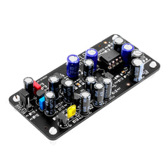
Thank you for purchasing a Toneloc Level-Loc Compressor Colour!
If this is your first DIY project ever, we recommend reading our Getting Started Guide.

Required Tools
You'll need the tools below to complete this build.

Soldering Iron
We recommend an adjustable-temperature station, such as the $40 Weller WLC100.

Solder
You can use 60/40 "leaded" solder or lead-free. We recommend 60/40 because it flows better and is easier for beginners to use.
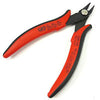
Wire Cutters
You'll need a pair of good "snips" for cutting of the excess leads after soldering.
Optional Tools
These tools aren't strictly necessary but can make your build a bit easier.

Multi-Meter
If you find the color bands on resistors a bit hard to read, you can use a meter to sort them with absolute confidence.
Desoldering Pump
If you accidentally solder something in the wrong place, a desoldering pump can save the day.
0. Resistor Calculator
Type in the value of the resistor you need and this tool will show you the corresponding color code.

Sort Components
Open your kit and sort the parts. You can either use the chart below or the handy Component Sorting Sheet (PDF).
| Designator | Value | Description |
|---|---|---|
| C1 | .1uF | Film |
| C13 | 2.2uf | Electrolytic |
| C15,C17 | .1uf | Ceramic |
| C16 | 100pf | Ceramic |
| C18,C19,C21 | 100uf | Electrolytic |
| C2 | 10nf | Film |
| C3,C6,C10,C11,C12 | 4.7uf | Electrolytic |
| C4,C7 | 10uf | Electrolytic |
| C5 | 1nf | Film |
| C8,C14,C20 | 47uf | Electrolytic |
| C9 | 680pf | Ceramic |
| Q1 | 2N5458 | Transistor |
| Q2-Q5 | 2N5088BU | Transistor |
| Q6, Q7 | PN2907A-AP | Transistor |
| R1,R32 | 8.8k | Resistor |
| R2,R11 | 680 | Resistor |
| R3,R22 | 4.7k | Resistor |
| R4,R12 | 33k | Resistor |
| R5 | 330k | Resistor |
| R6 | 120k | Resistor |
| R8 | 22k | Resistor |
| R10 | 220k | Resistor |
| R13 | 2.7meg | Resistor |
| R14,R29 | 100k | Resistor |
| R15,R18 | 10k | Resistor |
| R16 | 470k | Resistor |
| R17 | 180k | Resistor |
| R19 | 3.3k | Resistor |
| R21,R23 | 39 | Resistor |
| R24,R26,R38 | 47k | Resistor |
| R25 | 2.2k | Resistor |
| R28 | 9.1k | Resistor |
| R30 | 1k | Resistor |
| R31 | 1.2k | Resistor |
| R35,R36 | 100 | Resistor |
| R37 | 330 | Resistor |
| R39 | 2.2M | Resistor |
| R40 | 4.7M | Resistor |
| R7,R9,R20,R27,R33,R34 | 1meg | Resistor |
Populate Connectors
Solder IC Socket
Open bag one and find the 8-pin IC (integrated circuit) socket. Place the socket in the IC location on the PCB. Make sure to align the semi-circular notch on the socket with the notch on the PCB silk screen.
Flip the PCB over while holding the socket in place. Then solder the socket to the PCB.
Solder Header
Place the 8-pin header through the bottom of the PCB so that the long, gold pins are pointing away from the PCB. These are the pins that will mate with the Colour Palette. Solder the header to the PCB.
Set aside the plastic standoffs until the end of the assembly process and move on to bag 2.
Populate Resistors
Since the Toneloc contains a whopping 40 resistors, we recommend populating them one bag at a time. The next several steps outline the process of populating a bag of resistors, which should be repeated for each bag.

Identify Resistors
Resistors can be identified either with a multi-meter as shown or by their color-coded bands. Since the resistors in each bag share the same multiplier (1x, 10x, etc.), it's easy to identify the resistors by the first two color bands.
See this handy chart for identifying resistors via their color codes: Resistor Color Code Chart

Bend Resistor Leads
All of the resistors in the Toneloc mount vertically. To prepare them for insertion, bend one lead of each resistor 180 degrees so it's flush against the body.

Place Resistors
Place each resistor according to its value and part number. There are diagrams below showing the exact placement of the resistors in each bag.
Alternate the orientation of resistors that are next to each other. This reduces the potential for shorts between resistors.

Bend Resistor Leads Against PCB
After placing the resistors, bend their leads agains the bottom of the PCB. This will hold them in place when we turn the board over for soldering.

Solder Resistors
Solder the resistors to the PCB. Observe good soldering technique: heat the pad and lead for 2-3 seconds, apply a small bit of solder, and continue to heat the pad for another 2-3 seconds. Allow each solder joint 10 seconds to cool before moving on to the next one. The finished joints should be shiny and should have just enough solder to cover the pad entirely.

Trim Resistor Leads
Clip the excess leads with wire cutters. Clip as close as possible to the solder joint without clipping the joints themselves.
Populate Bag 2

Populate Bag 3

Populate Bag 4

Populate Bag 5

Populate Bag 6

Populate Remaining Components
Populate Bag 7

Populate the transistors and integrated circuit, taking care to place them in the correct locations and direction. If any of the transistors are swapped or inserted backwards, there will be smoke!
The orientation of the transistors is indicated by their shape on the PCB. The orientation of the IC is marked by a small notch on the PCB and the IC socket.
Populate Bag 8

Populate the small capacitors. All of these capacitors are non-polarized, so they can be inserted in either orientation.
Populate Bag 9

Populate the large capacitors. Despite being electrolytic (which are usually polarized), all of these are also non-polarized. You can disregard the "+" markings on the PCB.

Insert Standoffs
Snap the standoffs into the PCB so that they protrude outward on the same side as the 8-pin connector. The side with a rigid edge is the side you insert into the PCB.
Final Checks
Before you wrap up, check the following things:
-
IC orientation: Does the dot/notch on the IC align with the notches on the socket and PCB?
-
Transistor orientation: Does the shape of the transistor match the outline on the PCB?
-
Resistors: Do all of the resistor positions correspond the chart and/or sorting sheet?
-
Soldering: Is every solder joint shiny and clean? If one is cloudy or misshapen, try reheating it for 8 seconds and adding a tiny bit more solder.
-
Trimming: Are all of the excess leads trimmed down as close to the joint as possible?
All good? Congrats on finishing your build! Have a question or problem? Drop us a line.
Help Us Improve
1
2
3
4
5
6
7
8
9
10