XPF Assembly Guide
Damaged or Missing Parts All kits and parts are checked before being shipped to you. If something arrives damaged or if your kit is missing a part, please open a support ticket to inquire about a replacement. Missing parts will be replaced at our expense. Damaged parts should be returned for verification. If the part shows signs of use beyond what was necessary to determine that it was damaged, DIY Recording Equipment, LLC reserves the right not to replace the part.

Thank you for purchasing an XPF kit! Depending on your level of experience, you should be able to turn the pile of parts in front of you into a working piece of recording gear in about 30 minutes.
If this is your first DIY project ever, we recommend reading our Getting Started Guide before, well, getting started.
If you have any questions please don't hesitate to contact us for support.
Contents:
Assembling the XPF- Identify Resistors
- Place Resistors
- Bend Resistors
- Solder Resistors
- Place Capacitors and Bend Leads
- Solder Capacitors and Trim Leads
- Break R/C Sockets
- Place R/C Sockets (tape)
- Place IC Socket
- Solder IC Socket
- Bend IC Leads
- Install IC
- Place and Solder Header
- Install Plastic Stand-offs
- Trim Leads of Swap-able Resistors and Capacitors
Identify the 10 resistors by measuring them with your multi-meter or by reading their color codes. There are only 3 resistors that get soldered in this kit and they are the resistors that set the color of the Palette LED. The rest are used in various combinations in the sockets to set the cutoff frequency of the filter. More on that later.
These are the resistors that will be soldered:

And the swap-able resistors look like this:


When placing a resistor, bend the resistor leads so that they can easily fit into the PCB, and place them in the in the spots labeled with the matching values on the board.
With the resistor leads through the PCB. Bend them flat to the underside of the PCB. This will hold them in place when flipping the PCB over to solder.

Solder the resistors to the PCB. Heat each pad and lead for 2-3 seconds, apply a small bit of solder, and continue to heat the pad for another 2-3 seconds. Allow each solder joint 10 seconds to cool before moving on to the next one. The finished joints should be shiny and should have just enough solder to cover the pad entirely. After that, trim the excess leads of the resistors to get them out of the way.

Place the Capacitors on the PCB and bend their leads to hold them to the board. Then, solder the capacitors and trim their leads.

Included in the kit are two 20-pin sockets. From these we need to snap off a total of four 4-pin sockets to be placed in the various R/C positions on the board. A good way to break them is to hold them with needle-nose pliers and snap them by hand.

You will probably want to secure the sockets to the board somehow during soldering. Perhaps with tape as I've done here. Then flip the PCB over and solder the sockets in place.

Again tape may be involved in holding the socket to the board whilst you solder.

Solder all the pins of the IC socket in the usual fashion. Make sure the notched side of the socket is aligned with the outline on the PCB.

See how the pins of the IC protrude from the body at slightly wider than a 90 degree angle? In order to fit the IC into the socket, we'll need to bend the leads inward a bit. Set the IC on its side and press from the other side to bend all the leads at once. Then flip the IC over and do the same for the other side. When you are done the leads should be perpendicular to the body.

When placing the IC in the IC socket make sure the dot on the top of the IC is facing the notched side of the IC socket. This will ensure happiness.

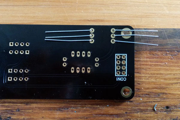
Place the 8-pin header through the bottom of the PCB so that the long, gold pins are pointing away from the PCB. These are the pins that will mate with the Colour Palette. Solder the header—there's no need to trim after soldering.

Snap the standoffs into the PCB so that they protrude outward on the same side as the 8-pin connector. The side with a rigid edge is the side you insert into the PCB.

Bend the Resistors so that their leads fit into the R/C sockets, then trim the leads leaving about 1/4 inch of the lead so there is something to attach to the socket.
Using the XPF
The XPF is design to either be used as a Low Pass Filter or a High Pass Filter depending on the orientation of the resistor and capacitors. If both resistors are in the sockets marked A and the capacitors are in the sockets marked B, then the XPF will act as a Low Pass Filter. If reversed the XPF acts as a High Pass Filter. Below are the default settings we've included in this kit, but don't let this stop you from trying out different values for more specific applications.
| Mode | R/C1 (A) | R/C1 (B) | R/C2 (A) | R/C2 (B) | Cutoff Frequency |
|---|---|---|---|---|---|
| HPF | C 0.1u | R 6.8K | C 0.1u | R 15K | 160 |
| HPF | C 0.1u | R 15K | C 0.1u | R 33K | 70 |
| HPF | C 0.1u | R 22K | C 0.1u | R 68K | 40 |
| LPF | R 68K | C 0.1u | R 150 | C 470p | 7200 |
| LPF | R 33K | C 0.1u | R 68 | C 470p | 15500 |