Z-In Preamp Input Control Rev B Assembly Guide
Safety Precautions, Warranty, and Disclaimer Improper soldering and handling of electricity can cause serious injury and damage to your property. Read and understand the instructions below before beginning your project. Follow the instructions, build carefully, and use the appropriate tools. Build at your own risk. DIY Recording Equipment, LLC is not responsible for any damage or injury resulting from the assembly or use of your Z-In kit. You are the manufacturer of your Z-In. It is your responsibility to turn this group of parts into a working piece of recording equipment. DIY Recording Equipment, LLC does not guarantee the success of your project and disclaims any Implied Warranty of Merchantability. Please open a support ticket for assembly support. Missing parts will be replaced at our expense. Damaged parts should be returned for verification. If the part shows signs of use beyond what was necessary to determine that it was damaged, DIY Recording Equipment, LLC reserves the right not to replace the part.

Required Tools
A Phillips-head screw driver, cutting pliers, soldering iron, and solder are all you need to successfully complete your Z-In build. A work-steadying tool such as the "Helping Hands" or Panavise is optional but highly recommended.
1
Before we begin soldering, identify the four resistors included in your kit. Resistors are identified by the electronic color code (Wikipedia).
2
Populate the PCB, beginning with the resistors. Insert R1-R4 in the positions indicated on the PCB. Bend the inserted leads against the bottom of the PCB to hold the resistors in place and then turn the PCB over for soldering.

3
Solder the resistors to the PCB pads, heating each joint for 5-8 seconds and applying a small dab of solder. After soldering, clip the leads as close to the solder joints as possible without damaging the joints themselves.

4
Solder switches SW1 and SW2 and mounting bracket H1 to the PCB and trim the leads of the switches. Only one of the mounting bracket's pins needs to be soldered and the pins do not need to be clipped. Solder the potentiometer VR1 and trim its leads. The rounded corners on the PCB silk-screen represent the back of the potentiometer.
5
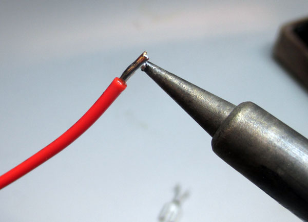
Remove the loose coating from the pre-trimmed hookup wires and tin the exposed leads by heating the leads and applying a small amount of solder.

6
Heat the pins of the XLR jacks for 5-8 seconds and fill the solder cups with a moderate amount of solder. Locate the numbers imprinted on the jacks to identify the pins. Then solder the hookup wires to the following pins by re-heating the solder cups while inserting the leads of the wires into the molten solder and then holding the wires in place while the solder dries.
Green → Pin 1
Red → Pin 2
Black → Pin 3
Optional Step: You can increase the balanced connections' common-mode noise rejection capability slightly by twisting or braiding the XLR wires together.

7
Break the small metal tab off of the potentiometer with a pair of pliers. Remove the nut from the pot's threaded bushing and put on 3/8" (larger) black plastic washer around the bushing.

8
Insert the XLR jacks into their respective holes and mount them loosely with the #4 (smaller) flat-head machine screws and nuts. We'll tighten them up during final assembly.

9
Insert the remaining leads of the hookup wires to the following PCB pads, solder them, and trim the leads.
Green → Chassis (three-pronged ground symbol)
Red → +
Black → -

10
Insert the black machine screw through the top of the case facing down into the case. Place the 1/8" (smaller) black washer over the screw from the bottom of the case.

11
Insert the populated PCB into the case with one hand while holding the screw in place with the other. Turn the screw slightly to set it into the threads of the PCB mounting bracket. Tighten the screw with a manual screw driver while guiding the PCB so that the switches and potentiometer are aligned with their respective mounting holes. Finally, tighten the XLR screws and fasten the lid to the case with the larger flat-head machine screws.

Complete!
Fasten the lid to the case with the #6 (larger) flat-head machine screws. Your Z-In is now complete and ready to make your mic preamps more versatile! Simply place the Z-In between your mic and preamp via XLR cables. -The Input Z control adjusts the impedance seen by your microphone between ~200-1kOhms -The Mic/Line button engages/disengages a 40dB input pad that allows your mic preamp to handle standard line input levels. When the Mic/Line switch is engaged, the Input Z control is bypassed. -The Polarity control changes the polarity of the output signal. When the button is engaged, the Z-In's output signal is 180 degrees out of phase with respect to the input signal. -Z-In is intended to be used with dynamic microphones only. Because of their active output stages, the variable impedance created by Z-In will not be "seen" by the microphone capsule and thus the Z-In's effect will be negated. Additionally, using the Z-In with phantom power can damage your mic preamp's phantom power supply. Do not engage phantom power on your preamp while using the Z-In.