Colour Palette Rev C/D (mkII) Assembly Guide
Damaged or Missing Parts All kits and parts are checked before being shipped to you. If something arrives damaged or if your kit is missing a part, please open a support ticket to inquire about a replacement. Missing parts will be replaced at our expense. Damaged parts should be returned for verification. If the part shows signs of use beyond what was necessary to determine that it was damaged, DIY Recording Equipment, LLC reserves the right not to replace the part.

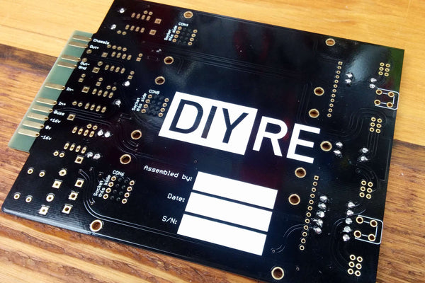
Thank you for purchasing a Colour 500-Series Palette mkII kit! Depending on your level of experience, you should be able to turn the pile of parts in front of you into a working piece of recording gear in about 1-2 hours.
If this is your first DIY project ever, we recommend reading our Getting Started Guide before, well, getting started.
If you have any questions please don't hesitate to contact us for support.

Required Tools
All that's required to build the Palette mkII is:
- Soldering iron and solder
- Wire cutters
- Phillips head screw driver
- 1/16" / 1.5mm hex key
If you don't have any of these tools, see our Recommended Tools page.

Optional Tools
The following optional tools may make your build process more pleasant or help you troubleshoot if something goes wrong:
- Solder sucker
- Multi-meter
- Tape
Populating Bags 1, 2 & 3

Sort Page 1
Print the Palette mkII Component Sorting Sheet (PDF) and sort the parts in bags 1, 2 & 3. You can identify the resistors by their color code or with a multi-meter.

Bend Resistors
Bend the resistor leads at the body so they can be inserted into the PCB.

Place Resistors
Place the resistors in their respective places on the PCB.

Bend Resistors Against PCB
Bend the leads of the resistors against the bottom of the PCB so that the resistors stay in place during soldering.

Solder Resistors
Now solder the resistors to the PCB. Observe good soldering technique: heat the pad and lead for 2-3 seconds, apply a small bit of solder, and continue to heat the pad for another 2-3 seconds. Allow each solder joint 10 seconds to cool before moving on to the next one. The finished joints should be shiny and should have just enough solder to cover the pad entirely.
Trim Resistors
Once all of the solder joints have cooled, use your clippers to trim away the excess leads. Your goal should be to clip as close as possible to the joint without clipping the joint itself.

Cut Fuses from Tape
Use wire cutters to remove the fuses F1 and F2 from their packaging tape.

Populate Small Caps and Fuses
As you did with the resistors, place, bend, solder, and trim the parts in bag 2.
FAQ: Are these parts polarized? Nope, insert them any way you like.

Solder IC Sockets
Place the four 8-pin IC sockets in the U1-U4 positions on the PCB. Make sure to align the notch in the sockets' plastic with that one the PCB. Tape the sockets in place, solder them, then remove the tape.
Now place and solder the 4-pin, integrated diode bridge in the BR1 position. Make sure to align the design on the diod bridge's body with that on the PCB silk screen.

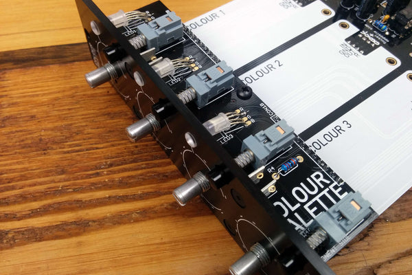
Populate Colour Sockets
Flip the PCB over and place the 8-pin Colour sockets in the CON4-CON6 positions. Tape them in place, solder, and remove the tape. Make sure that you have placed the sockets on the underside of the PCB before soldering!
Populating Bags 4 & 5

Sort Page 2
Sort the parts from bags 4 and 5.

Populate Large Capacitors
Note that these caps are polarized, meaning they must be inserted in the PCB in a certain direction. The longer lead is the positive terminal, while the strip on the body corresponds to the negative terminal. Place the capacitors on the PCB, taking extra care to place the longer lead closer to the "+" marking on the PCB. All of the capacitors should face the same direction.
Once you've double checked their orientation, bend, solder, and trim the caps.

Populate Mounting Brackets
Flip the PCB over and insert the brackets from the bottom of the PCB. Solder them, but do not trim the leads.

Populate Potentiometers
Solder the potentiometers in positions VR1-VR4 and trim the excess leads.

Tape and Solder Daughterboard (DB) Sockets
Tape and solder the 12-pin sockets to the CON1A and CON2A positions.

Insert Headers and Standoff
Insert the 12-pin headers loosely into the sockets. Also loosely thread the standoff into the hole between the two sockets.
Populating Bags 6, 7, & 8

Sort Page 3
Sort bags 6, 7, and 8.

Populate R4
Place, solder, and trim R4 on the DB.

Populate DB Brackets
Place the remaining sockets through the top of the DB and solder.

Populate Switches
Place the switches in SW1-SW4 positions. Tape them firmly in place so that the plastic feet of the body are flush with the PCB. Then solder them, trim the leads, and remove the tape.

Attach DB
Place the DB over the headers CON1B and CON2B and screw it to the standoff. Press the headers up so that the black, plastic square-posts are flush with the bottom of the DB. Then solder the headers to the top of the DB.

Place LEDs
Place the three LEDs in the LED1-LED3 positions. Place the longest leads of each LED through the holes marked "-". Double check the orientation of the LEDs before moving on.

Bend LEDs
Hold the LEDs upright and press them down so that their leads rest against the top of the motherboard. (This, it turns out, is the perfect place to bend their leads.) Now bend the LEDs forward towards where the front panel will be.

Solder LEDs in Place
Solder just one lead of each LED from the top of the DB.

Bend LED Leads Against PCB
Now remove the DB and bend the leads of the LEDs away from the 12-pin headers for soldering.

Solder LEDs from Bottom
Solder the LEDs and trim their leads. Then place the DB back on the MB and screw it down.

Place ICs
Insert the ICs U1-U4 into their respective sockets. Not all of the ICs are the same! Double check their positions in the Component Sorting Sheet (bag 7).
Set the IC on top of the socket, making sure to align the semi-circular notches. Double check this! Now apply pressure with one or two fingers to press the IC firmly into the socket.
Attach Front Panel
Snap the black caps onto the switches and press the LED lenses through the front panel. Then screw the front panel onto the PCB assembly via the four mounting brackets. If necessary, adjust the position of the LEDs so that they are as close as possible to the lenses.

Attach Knobs
Now for the trickiest part! Fastening the knobs in the perfect position takes a bit of patience and care. First, turn all of the shafts to the 12 o'clock position (10 detents from full CW or CCW). Second, place the knob over the shaft so that the white indicator line points to the middle of the top position. Then place a credit or business card between the knob and front panel and fasten the knob with the two set screws.

Complete!
Congratulations on finishing your Colour 500-Series Palette mkII! If you had any trouble or have suggestions for improving this guide, please contact us via the support page.