news
"Explain Like I'm 5": Audio Transformers May 25, 2017 12:28
What are transformers?
Transformers are those huge, heavy, primitive-looking parts you’ll see in both vintage and modern audio gear.
They look something like this:

Or this:

Or this:

What do audio transformers do?
A lot of things! I guess that’s why we keep them around, primitive and expensive as they are.
Transformers do a lot of different jobs in audio gear, including:
- Stepping voltages up or down: increasing output level of microphones, bringing instruments down to mic level, etc.
- Providing balanced inputs and outputs
- Impedance matching
- Eliminating ground loops
- Blocking DC while passing audio signal
How do transformers work?
A transformer is just two long wires wrapped around one magnetic core. Signal passes from one wire to the other, but the wires don’t touch. What sorcery is this?! It’s a funny feature of our universe called “electromagnetism,” where electric current creates magnetic fields and vice versa.
![]()
Modified and reused under the GNU Free Documentation License
The electrical current running through first coil of wire (the “primary”) creates a magnetic field in the core. This magnetic field then induces a corresponding voltage in the second (“secondary”) coil. Voila! We now have the same signal at both sides of the transformer without a single electron making the journey from one side to the other.
How do transformers step voltages up or down?
We only get that same exact signal on both sides when both coils have the exact same number of turns around the core. By changing the number of turns in each coil, we can directly change how much signal is transferred between them.
For example, if the primary coil has 200 turns and the secondary has 100 turns (we call this a “turns ratio” of 2:1), only half the signal will be transferred. This is called a “step down” transformer. However, we could turn that same transformer around and use it as a “step up” transformer to double the signal!
If that sounds too good to be true (free gain!), it’s because we’ve only considered half of the equation—if a transformer steps up voltage, it steps down current by that same amount, and vice versa. Another way of saying this is that transformers can’t create or destroy power (power being the product of voltage and current). You could think of transformers as trading voltage for current, while power stays the same.
For example, let’s say a 1:2 transformer sees an input of 1 Volt at 1 amp current. At the secondary, the voltage will be stepped up to 2V, but with only 0.5 amp of current available. So a 1:2 transformer for voltage is a 2:1 transformer for current.
How do transformers match impedance?
Sometimes it’s important to match the impedance of two devices that are being connected (see "ELI5: Impedance" for more on that). For example, your guitar won't sound very good if you plug it right into a mic preamp—the output impedance of the guitar is just too high to transfer all its signal to the preamp. So we use a DI box to step the guitar’s output impedance down to mic level.
And guess what's in a passive DI box—a transformer! Transformers can step impedance up or down in the same way they do with voltage and current. Except whereas they change voltage by the turns ratio and current by the inverse of the turns ratio, they change impedance by the square of the turns ratio.
So let’s look at a DI box as an example. A typical passive DI box transformer has a turns ratio of 12:1, which means it will step down the guitar’s output impedance by 144:1 (12 squared). A typical output impedance for a single coil pickup is around 20k Ohms, which our DI box will step down to 138.8 Ohms, which is typical of a microphone. Now we can run that guitar directly into our mic preamp with no impedance issues. Transformers win!
Why do transformers sound so good?
Of course, we don’t just keep transformers around to do technical jobs—they also sound really good. There are a couple reasons for this, mostly having to do with the unique ways in which they "fail" to be perfectly clean and linear.
Like all analog components, transformers clip when given too much signal. Transformer clipping happens when the core saturates and can't contain any more magnetic flux. This sets a hard limit on the amount of signal the transformer can pass and generates harmonic distortion.
What makes transformer saturation so lovely is that the distortion it creates is inversely proportional to frequency. Which is a fancy way of saying transformers create more warm, gooey, low-frequency distortion and less harsh, bright, high-frequency distortion.
Transformers also exhibit another distortion phenomenon called "hysteresis." This is where the core, after getting magnetized by a signal, stays magnetized for a short period of time after the signal is removed. Hysteresis creates low-frequency, harmonic distortion at all signal levels, not just when the core is saturated. This same effect is a large part of the desirable sound of analog tape.
Why is transformer inductance important?
Inductance is a measure of how well a component converts voltage into magnetic flux. We're concerned with inductance in audio transformers because higher inductance in the primary coil translates to better low-frequency response. Inductance can be increased with either more windings or a more permeable core material (see below).
How does core composition affect the sound?
Different materials have different abilities to contain magnetic flux—this is called “permeability.” Core materials with higher permeability create higher primary inductance, and therefore better low-end response. However, more permeable core materials will also saturate faster than less permeable ones. Ah, nature, where everything's a tradeoff!
The most common core materials for audio transformers are M6 steel (steel with a bit of silicon) and nickel/iron alloys. Cores with high nickel content are more permeable and more expensive, with less hysteresis than steel cores.
In general, steel will have higher distortion at normal signal levels due to hysteresis, while nickel will have higher distortion at higher levels, due to saturation. For this reason, you'll often find high-nickel cores in high-quality transformers designed for lower signal levels, and steel cores in cheaper transformers or those designed for high signal levels.
What’s a zobel network?
Transformers, like all other parts that exist in the real world, have unintended effects called “parasitics”; ie, extra resistance, inductance, and capacitance that an ideal transformer would not have.
Sometimes these parasitics will combine to cause the transformer to ring in the audio range. That is, if fed a certain frequency, the transformer will keep ringing at that frequency even after the signal is removed.
A Zobel network is a simple, passive filter consisting of a resistor and capacitor placed after the transformer to eliminate ringing.
What'd I miss?
Thanks for reading! Let me know in the comments below if you have any questions about transformers I didn't answer.
"Explain Like I'm 5": Printed Circuit Boards December 1, 2016 13:23
What is a printed circuit board (PCB)?
Before I answer that, let's talk about how circuits were made without PCBs. Before the advent of PCBs, people soldered components and wires right to each other, usually with the help of some sort of rigid board. For example, the technique shown below is called "turret board," where wires and parts are soldered to each other and to turrets to complete a circuit.
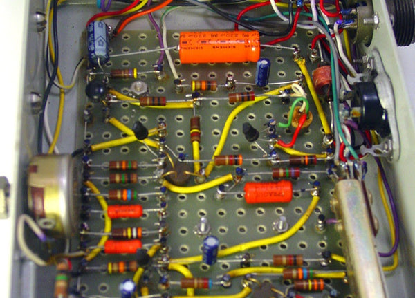
As you can see, assembling electronics used to take a lot of time, skill, and focus! Then PCBs came a long and made everything a easier by building all those wires right into the board itself.
PCBs are rigid boards with pre-wired circuitry, plus some extra perks like soldermask and silk-screening (more on those to come). So these days, instead of painstakingly cutting, bending, and soldering each connection, the assembler just has to solder each component in the right place and the PCB does the rest.
What are PCBs made of?
PCBs are made of several layers, like an onion parfait. These layers are: substrate, copper, soldermask, and silk screening. PCBs can have several of each of these layers, but most audio PCBs are "two-layer" boards (top and bottom) with this makeup:
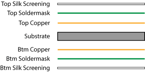
Let's take a look at a very simple PCB, our L2A Passive Re-amplifier, layer-by-layer. To keep things simple, we'll only show the top copper, soldermask, and silk-screen layers.

The core of a PCB is fiberglass. Its job is to be rigid (to hold the parts in place) and non-conductive (so electricity won't pass from one side of the PCB to the other). The holes you see in the substrate are for mounting components to the PCB.

This is where the circuit happens. The copper circles you see are called "pads"; this is where the parts get soldered to the board. The lines are called "traces"; this is what carries the electricity from one part to another. There are only a couple of traces visible here because most of them are on the bottom side of this particular PCB.

Although the pads and traces are made of the same thing, we only want to solder to the pads. So we cover the traces in a layer of polymer called "soldermask" that keeps us from getting solder on the traces.

Finally, we print some silk-screened labeling so that the humans can know where to put the parts.
Can I make my own PCBs?
Yes! Start by learning your way around an ECAD (electrical CAD) program. The most popular free programs are EAGLE, DipTrace, Upverter, and KiCad. My favorite of the bunch is Diptrace, though EAGLE is somewhat of an industry standard among DIYers. Here's what the L2A board looks like in DipTrace:

The best beginners' guide I've found to PCB layout is Dave Jone's PCB Design Tutorial (PDF).
Once you've got a layout, you can either order your PCB from a manufacturer, or etch your own at home.
OSHPark is an amazing, game-changing service that charges only $5 per square inch for three copies of your PCB. Unless you plan to make lots of PCBs at home, you won't beat that price rolling your own, and you certainly won't approach the same quality.
If you just love the idea of making your own PCBs or can't wait for OSHPark to deliver, Make Magazine has a great rundown of all the ways you can roll your own.
Any other questions about PCBs you like me to answer?
Let me know in the comments!
"Explain Like I'm 5": Opamps July 21, 2015 14:09
What are opamps?
Opamps (or op-amps, or operational amplifiers) are small, inexpensive integrated circuits that can be used to do a ton of different things in audio electronics. They can apply gain or attenuate a signal, create filters, present desired input/output impedances, oscillate at specific frequencies, etc.
They’re usually manufactured on a black, spider-like component with at least five terminals:
- +Power
- -Power
- +Input
- -Input
- Output
What do opamps want?
Instead of talking about how opamps work from an electronics perspective, it’s easier to think about what they want. Opamps want their inputs to be equal all the time. So if the voltage at both inputs is 0, the opamp is happy–it doesn’t need to do anything at all. But the second we change the voltage at one of its inputs, the opamp will jump into action immediately to give the other input that same voltage. Absolute equality–that’s all it wants.
Opamps are so committed to this single desire that they will burn themselves out in a plume of noxious smoke before admitting defeat.
How do they get what they want?
Opamps use their outputs to make their inputs equal. But they can’t do this on their own–they need us to provide a feedback path. Let’s say we kindly oblige and solder a wire between the output and - input pins. (This is called negative feedback.) Now whatever voltage the opamp sends to it’s output gets immediately sent to the - input as well. In other words, if the + input is fed a certain voltage, the opamp can immediately make the - input the same by adjusting its output voltage. In other words, it can get what it wants!

Negative feedback
Now let’s do that with numbers so you can see what it looks like. Say we connect a microphone with a 1V output to the opamp’s + input. The opamp wants to make - input 1V as well so it sets its output to 1V. And since we’ve attached a negative feedback wire, that 1V is immediately sent to the - input. Now both inputs are sitting at 1V and the opamp is happy.
How we make them do what we want?
That’s all well and good, but if we stopped there the opamp would only be good for passing unity gain. The real fun comes in replacing that feedback wire with some more interesting components. Let’s say we replace it with two resistors configured as a voltage divider.

A voltage divider in the negative feedback loop
These resistors will take the voltage from the output and cut it in half before it reaches the - input. Let’s go back to our example from the previous section. If the output were still set to 1V, the - input would be at only 0.5V. And that’s not what the opamp wants! So now it adjusts its output to 2V to get 1V back to the - input. The opamp is happy again and our microphone signal is 2x (6dB) louder at the output of the opamp.
And gain is just the beginning. We can put all sorts of stuff in the feedback loop: capacitors and inductors for filters, diodes for clipping, transistors for variable gain–you can even put other opamps in there! The point is that the opamp just wants one simple thing–to make the inputs equal–and we can make it do all sorts of stuff just by making it work harder to make that happen.
How do opamps work?
I honestly have no idea. I’ve never designed one or even bothered to look at one’s schematic diagram. But that’s the beauty of integrated circuits: you can treat them like a black box. If you understand their specs and theory of operation, you can use them without knowing what’s going on inside.
Why are there so many kinds of opamps?
All of design is basically managing tradeoffs: more gain vs. more noise, greater bandwidth vs. less stability, greater precision vs. higher cost, etc. There are hundreds of different opamps and they all do the same thing but make different tradeoffs. So one opamp may be ultra-low noise, but have stability issues at high gains. Another may be very low cost but have lots of noise. And so on.
What are discrete opamps?
99% of opamps you’ll come across are monolithic, as opposed to discrete. They look like the spider thing below and are manufactured in massive quantities on silicon chips.
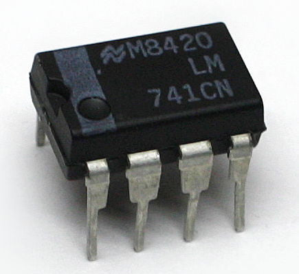
A standard monolithic opamp IC
But some folks in the audio community are not content to pick from the variety of monolithic opamps available. They prefer to roll their own by placing individual components on a printed circuit board. They are big and expensive and usually sport “worse” specs than even low-end monolithics, but they have certain benefits like being proprietary and high-margin entirely customizable to suit the designer’s ears.

Image courtesty of 6SN7, licensed under a Creative Commons License
Do different opamps sound different?
There's much debate over how significant the audible differences are between different opamps. Some people (often musicians) claim to hear a "night and day" difference when they swap the opamps in an old piece of gear. Some people (often engineers) claim there's no difference at all.
I've spent a good bit of time listening to different opamps in a controlled environment and my take is that audible differences between opamps are vanishingly small when they're operated in their linear range. When you start to ask them to do stuff beyond what on their spec sheets, all bets are off.
So, swapping an opamp that's just a buffer between two stages in a compressor? Probably not gonna hear much of a difference. Swapping opamps in a circuit with a hot input signal and excessive amounts of gain? You will hear major differences, akin to using two different mic preamps to apply a lot of gain.
Did I miss anything?
I hope that helped clarify things a bit! Is anything unclear? Let me know in the comments if you have any other questions about opamps I can answer.