news
73P Mic Preamp Design Log October 24, 2023 13:41
In 2018, I published a post about a “Mystery Project” that involved researching, building up, and listening to various circuits from vintage Neve consoles. In the five years since then, that project has evolved into a 500-series mic preamp kit, coming in early 2024. What follows is a preview of the “Design Notes” that will accompany the kit.
Picking a Circuit
Our intention with this project was to recreate the mic preamp from the 1073 preamp/EQ module as authentically as possible. (Neve actually had their own module with just the mic preamp called the 1290. But since 1073 is the model most people are familiar with, we’ll call it that.) In surveying the current field of 1073-esque preamps, we noticed two distinct approaches; we’ll call these the “three-stage” and “two-stage” designs.
The original 1073 (and 1290) used three stages. This approach uses two high-gain preamp stages (yes, I know it’s confusing for a preamp to contain preamps, but that’s what they’re called), and one low-gain output stage. Neve split the gain between stages this way to keep distortion consistently low at all gain settings. Most modern clones are three-stage preamps.
The two-stage approach has only one preamp stage, followed by the output stage. This is based on yet another Neve module, the 1272 line amplifier. Around the 90’s people started racking these modules and adding gain switches to convert them into mic preamps. Since then, several companies have made two-stage preamps, often named after the 1073 even though they are closer to the 1272. These can still sound great, and some are highly regarded.
The two-stage approach is appealing because it reduces cost and complexity. This is especially true for a 500-series module and DIY kit. However, after researching the circuit and evaluating a vintage 1272, we decided against it. In addition to being more faithful to the 1073, the three-stage design allows for more gain and better performance.

The preamplifier circuit, of which there are two in the 1073 and one in the 1272.
This is clear if we look at the original modules. The 1073 provided up to 80dB of gain, the 1272 only 50dB. From 0-50dB the preamps are identical, but from 55-80dB, the 1073 engages the third amplifier stage. Modern, two-stage preamps achieve more than 50dB by increasing the gain of each stage. This pushes the amplifiers beyond what they were asked to do in the original designs. This isn’t necessarily a bad thing, but it’s not how Neve designed their mic preamps. It’s telling that Neve never used the 1272 as a mic preamp, and instead went to the expense of the third stage. For this reason we decided that the three-stage design was the clear choice.
Adapting to 500-Series
The first challenge was how to fit the 1290’s many parts, including two big transformers and one giant transistor and heatsink. However, this was a straightforward problem that just required some grunt work. We also aimed to replicate the grounding scheme of the original. Neve managed ground currents carefully between amplifier stages to keep noise low. We recreated this on the 500-series module by giving each stage its own ground pour, which is tied to the others via a bus wire which runs along the bottom of the module back to the card-edge connector.

Our most recent prototype, with everything fitting in a single 500-series slot. We have at least one more round of prototyping to go, with an improved layout and the TIP3055 transistor.
The more complex problem was how to handle the power supply. The 80-series consoles ran on a unipolar 25v power supply. The 500-series on the other hand uses a bipolar +/-16v supply. Therefore, some form of conversion needs to happen to power the 1290 correctly from the 500-series rack.
We considered several options. First, we looked into adjusting the 1290 circuit to run on +/-16v. A bipolar +/-16v supply can also be used as a unipolar 32v supply by treating -16v as ground. In this scheme, some resistor values would just have to be adjusted to make the transistors bias correctly. This has the benefit that no regulation or DC-DC conversion is required, and some high-end 1290-style preamps have used this approach. However, we quickly realized that scaling the bias resistors would also require scaling gain setting and feedback resistors, which would in turn require scaling capacitors, and so on until the circuit barely resembled the original.
The next approach was to regulate both power rails down from +/-16v to +/-12v, thereby creating 24v between the two rails. This is the most common route taken by existing clones. It has the drawback of requiring two regulators or an integrated DC-DC converter, but it does not require any changes to the 1290 circuit.
We were set on this path when we realized that we could also achieve 24v with a single regulator, by using -16v as ground and regulating +16v down to +8v. This freed up some precious PCB space and eliminated a potential failure point. So we decided on this scheme, but with an important twist: we “deregulated” the +8v rail to get even closer to the original.
The Sound of the Power Supply
An overlooked aspect of the original console is the design and performance of the power supply. Nothing in analog audio is truly “outside the signal path.” Everything in a piece of gear from the chassis to the power supply affects the sound. The power supply affects audio in two ways: by being quiet or noisy, and by being “stiff” or “saggy.” The first is straightforward—we want to keep noise as low as possible. The second describes the supply’s ability to deliver current while keeping the voltage stable. A “stiff” power supply never drops below its rated voltage. A “saggy” power supply will momentarily drop below the rated voltage when faced with a big spike in the demand for current. These spikes come from especially loud, low-end-heavy sources and increase with gain and level. The sag creates distortion and compression which are part of the sound of the preamp.
Modern regulator chips and DC-DC converters are invariably as stiff as possible. So in order to recreate the sag of the 80-series power supply, we simply used the same regulator technology Neve used. Our +8v rail is generated utilizing a zener shunt regulator with a large pass transistor. Think of it this way: if you had a vintage 80-series console, would you replace the power supply with a modern one?
Selecting Parts
Transformers were the most straightforward component to choose. Carnhill transformers are the de facto standard for anything vintage Neve. The blue input and red output transformers have even become visually iconic in their own right. We tested some options from OEP, Sowter, and Ed Anderson, but found no reason to deviate from the Carnhills.
All of the transistors we auditioned for the 73P.
Transistors do the work of amplifying the signal. The 1290 card uses two types: eight small-signal transistors, and one power transistor to drive the output transformer.
Our process for choosing them was to compare several currently-available options to a vintage set taken from an 80-series console. These were BC109C for the small-signal, and a Newmarket 2N3055 for the output.
Our takeaway was that transistors are important to the sound, but only when they are saturating. That is, when the preamp was delivering a clean signal with no noticeable saturation, we heard little-to-no difference between the transistors. But once they started to clip, audible differences did emerge.
However, even in saturation the differences are not night-and-day. We’re talking about the kind of differences that can only be positively identified with good monitoring and careful flipping back and forth between samples. This is confirmed by Neve’s own approach. When they were making the 80-series consoles, Neve used various small-signal transistors, including the BC107C, BC109C, BC184L, BC184C, BC114 and various brands of 2N3055. Additionally, manufacturing tolerances were much looser in those days, so batches of the same transistor might be as different as one transistor was to another. The takeaway, however, is not that every 80-series module sounded significantly different. Rather, it’s that the circuit is designed to be highly forgiving so that almost any transistor can drop in and sound basically right.
Many of the transistors Neve used are still in production, including the BC107/BC109, BC184, and 2N3055. However, manufacturing processes have changed so much since then that there’s no guarantee that these would sound anything like their vintage counterparts. So we also tested several other transistors that have been used in this circuit, including the BC550, BC548, 2N4401, MPSA06, MPSA18 for small-signal and the TIP3055 for output. We spent several days exclusively listening to transistors on various samples and at various gain levels deciding on the BC109C and TIP3055.
Capacitors often get a bad rap as something to avoid in audio circuits (have you ever seen “capacitorless signal path” in ad copy?), but they are key to the sound of this circuit. The 1290 uses three types: polystyrene, tantalum, and aluminum electrolytic.
We know from our listening tests for previous designs that polystyrenes and tantalums have their own sounds which cannot be achieved with more modern options. As such, we didn’t consider replacing them.
Electrolytic capacitors required a deeper dive. In our experience, different manufacturers, series, and even voltage ratings of the same value electrolytic capacitor can sound different. So we wanted to make sure to do our due diligence on this front.
The main difficulty lay in finding a gold standard to measure against. Electrolytic capacitors have a shorter shelf life than polystyrene and tantalum, so any that could be pulled out of an 80-series console would have long gone bad or at least changed their performance too much to be a gold standard. Additionally, any consoles still in use have been recapped (had the electrolytic capacitors replaced) several times. This further complicates the search for a gold standard. That is, should the reference point the caps that “Rumours” passed through in 1977 or the ones that recorded “Nevermind” in 1991?
So the best we could do is to trust the techs who have been recapping these consoles for years. They generally recommend the BC 031 series for both sound and form-factor. So we compared a set of 031s against our favorite Panasonic FR series on the same BA283 card. The result was that we found the FR series to be practically indistinguishable from the 031. Based on this, we opted for the FR series as the radial (vertical) mounting style fits better in the 500-series space constraints.

Coming Soon: The 73P Preamp Kit
As you can tell by this point, we’ve come a long way with this project and are just putting on the finishing touches. We plan to release the 73P Mic Preamp in early 2024. The exact details, including pricing and launch date will be announced this winter. Please subscribe to our newsletter via the footer below to find out immediately when the kit is ready to order. And thank you for following along!
Sonic Varnish July 19, 2022 11:22
Editors note: the following is an article written by Allen Farmelo. This article made a big impact on me when I first read it about 10 years ago, and it certainly played a role in inspiring the Colour Format. It's since disappeared from the internet, so I'm very happy to be able to re-post it here with the author's permission. - Peterson
When I was about ten years old my father drove an old-school Mercedes with a wooden dashboard that I thought was one of the most beautiful things in the world. Its glassy finish fascinated me because I could see every detail of the wood grain. I asked my father how it got like that and he explained varnishing to me, claiming that “Mercedes probably put at least twenty coats on.” Not long after that I bought an old skateboard that was horribly beat up, and I told my father that I wanted to varnish it to look like the Mercedes dashboard. Down in the basement we stripped the nasty paint off that wooden skateboard and started applying thin layer after thin layer of varnish with careful wet sanding and cleaning between each one. It was taking forever, and after twelve coats I proclaimed that the skateboard was done. It was glossy – not quite glassy – and I’d certainly learned about varnishing. It’s a lot of subtle work, and no one layer really seems to do all that much.
Harmonic Distortion is Sonic Varnish
Today when people ask me how I achieved certain sounds in the records I work on, I struggle to answer the question because it’s such a multi-faceted thing. Then it occurred to me that you could think of it like applying many small layers of varnish, except that instead of applying clear-coats of lacquer I apply layers of very subtle harmonic distortion. The word ‘distortion’ here is nothing like the overdrive and fuzz we talk about when discussing guitar pedals and amps. In fact, most people with untrained ears can’t hear a single layer of truly subtle harmonic distortion because it only gently changes the sound, and sometimes it’s so subtle that it’s basically inaudible.
All audio equipment (including most plug-ins) imparts a small percentage of harmonic distortion, and this percentage is called total harmonic distortion, or THD. THD can be understood as the amount of extra sound generated by the electronics in the piece of equipment itself. Some audio gear is sought solely for the character of its harmonic distortion and is said to be very “musical,’ meaning that we humans tend to like how thing sound when it goes through these circuits. Equipment famous for harmonic distortion includes Neve preamps, Fairchild compressors and Pultec EQs. These are units that people will run sounds through just to pick up harmonic distortion that the circuit generates even when it’s not particularly doing anything to the signal. We call it tone, vibe, mojo, fairy dust, goodness, sweetness, fatness, warmth, size, girth, a sonic halo and all kinds of other names, but what we’re basically describing is that subtle percentage of extra sound that the circuit adds to the signal. For this article I’m calling it sonic varnish.
It’s important to remember that most undeveloped ears wont be able to tell the difference between a sound going through a Pultec EQ set at neutral and a sound that isn’t. Over and over again I’ve inserted pieces of gear in and out of signal chains to show people the difference. If their ear is untrained, or still developing, they squint intently at the speakers for a bit then open their eyes, lean back in their chair and say, “I can’t really tell the difference.” Could I tell the difference between a Mercedes dashboard that had twenty-one coats of varnish as opposed to twenty? I’d probably squint at them and give up as well, but a professional wood worker might be able to see the difference. And – far more importantly – a pro will know which varnish to use, how to apply each coat, and which of those coats should be the last in order to achieve the desired result. It’s the same with sonic varnish. One layer doesn’t do all that much, but many layers add up to a finished sound that anyone can hear and say, “Yeah, that sounds really cool.”
Applying the Layers
I believe that one of the reasons we love the sound of records from the 60s and 70s so much is that the sounds were achieved by the (often unintentional) application of many subtle layers of harmonic distortion. Take a Beatles record like Sgt. Peppers recorded on 4-track – a classic example. I’m not sure of the historical accuracy of this explanation, but lets assume that Ringo’s drums were tracked early on. Then those drums were bounced back and forth between the four tracks of tape as they made room for further overdubs. For the sake of argument, let’s guess that Ringo’s drums made two bounces after they were tracked. Each time they bounced, they picked up the sound of the console’s electronics, the tape machine’s electronics and the sonic character of the tape itself. If you count each stage as a layer of varnish, that’s roughly seven layers (preamp, compressor, tape, preamp, tape, preamp, tape). Then you mix the record, which adds another layer, then master it, then play it on your home system (which will have a THD rating, too), and we’re somewhere in the realm of twelve layers of sonic varnish before you hear Ringo’s drums.
RINGO’S DRUMS
- Layer 1: mic
- Layer 2: console preamp
- Layer 3: compressor
- Layer 4: tape machine
- Layer 5 & 6: bounce 1 (console and tape)
- Layer 7 & 8: bounce 2 (console and tape)
- Layer 9 & 10: mix to mono tape (console and tape)
- Layer 11: mastering
- Layer 12: your home system
Now compare that to a modern home recording. Typically the signal is recorded into a consumer grade preamp, processed with a compressor plug-in and bounced to disc.
TYPICAL MODERN HOME RECORDING
- Layer 1: mic
- Layer 2: preamp
- Layer 3: plug-in compressor
- bounce
- Layer 4: your iPod
The way I see it, this signal has had two chances to receive a coat of sonic varnish. During the recording it hit the preamp and then the compressor plug-in to achieve a second layer. Someone with only two layers of consumer grade varnish will still want to make the most of the recorded sound, so she or he is likely going to try to make each of those two layers as thick as possible. I see this all the time, and a slew of common amateur techniques have evolved. What I see most of is way too much compression, double and triple tracking of parts to add dimension, and the use of distortion plug-ins for a lo-fi sound that is more often a final ditch effort at sounding interesting than an aesthetic choice. People will try anything to make those two or three layers as thick as possible.
The temptation to overuse any one of these stages is strong because the sound just isn’t going to pop out of the speakers if you’re doing subtle work. This lack of sonic excitement is confounded by the lower quality components in consumer grade equipment, too. When you start to overuse any of these layers you acquire obvious sonic artifacts that will change the nature of the source sound to such a degree that the characteristics of the processing itself can overtake the characteristics of the original sound. A kind of haze emerges between the sound and the listener, and when you multiply that by however many tracks you have in the mix, things can get downright foggy. I hear it all the time and the result is simply unremarkable. As my father will still tell you, thick layers of low-quality varnish look horrible. They don’t dry evenly, bubbles get trapped in the varnish, and brush strokes are often visible. Rather than showing off and accentuating the amazing colors, details and depth of the original wood, you end up seeing the varnish and the artifacts of its application. The exact same thing happens with thick layers of consumer grade sonic varnish. There’s no short cut. You want your skateboard to look like a Mercedes? Start layering. You want your mix to sound like a great classic album? Start layering.
Modern Varnish Mixtures
I use a combination of digital and analog gear to achieve my layers of sonic varnish, and I chose each layer very carefully to emphasize a particular quality in the sound that I think serves the artistic vision of the project. And I always have my eye on the final mix. For example, if I know I’m going to mix to tape, I have that in mind as I compress the vocal because I know the vocal will “sit down” a bit more once the mix has hit tape. As I apply each coat of sonic varnish, I have the next layers in mind so that I don’t apply any one layer too thickly. I’m interested in the cumulative result of many subtle layers. Let’s take a look at a particular vocal sound to get a sense of what I mean. This is from a very sparse record of which I’m particularly proud of the vocal sound:
- TRACKING
- Layer 1: Vintage Telefunken U47 (tube microphone)
- Layer 2: Chandler TG2 mic preamp
- Layer 3: Tube Tech CL-1B Compressor
- Layer 4: Cranesong HEDD converter (a touch of its Pentode processing)
- INDIVIDUAL TRACK PROCESSING DURING MIXING
- Layer 5: API 550a EQ
- Layer 6: Tube Tech CL-1B hardware compressor
- FULL MIX PROCESSING
- Layer 7: API 2500 stereo bus compressor
- Layer 8: Dangerous Audio BAX EQ
- Layer 9: Studer A-80 1/2″ tape recorder
- ANALOG TO DIGITAL PROCESSING
- Layer 10: Studer output stage
- Layer 11: Cranesong HEDD A-D conversion (with a touch of Pentode processing)
Each and every one of these eleven layers is doing something so subtle that very few people can really hear the difference. But, each and every one is just as important to the overall sound as the one before it or the one after it. Use a different mic and the sound will change. Use a different preamp and the sound will change. Use a different converter into the DAW and the sound will change. Use a different bus compressor or tape machine and the sound will change. Each and every layer is equally important, while no single layer is all that important on its own.
My personal theory about why this technique works is that you’re never letting a single piece of gear overtake the original sound. Instead, you’re letting each piece of gear impart just a little bit of harmonic distortion – a little mojo, a small halo, a bit of warmth, a little extra size – and then moving on to the next piece of gear that’s going to impart another kind of harmonic distortion. Maybe the preamp warms up the mic a bit, and maybe the compressor puts a little halo around things, and maybe the tape machine adds a certain depth, and maybe the converter adds a little something-something. Layer by layer the varnish becomes thicker while each layer remains relatively transparent. The original sound is still in tact, but it has acquired all of these wonderful, subtle qualities along the way.
Gain Staging – The Craft of Varnishing
With wood, layers of varnish go on rather simply, one at a time, but there is still a craft to it. My coats of varnish on that skateboard weren’t nearly as well applied as my fathers because he had years and years of experience with a brush in his hand. He had the craft that told him how far to dip the brush, how hard to push that brush against the edge of the can to remove excess varnish, where to begin and end his strokes and how hard to push as he made them, and he knew when enough was enough. He knew how to varnish.
In audio, how you varnish is called gain staging. Gain staging refers to the rather complex craft of knowing where the optimal (or intentionally not optimal) operating levels are for any piece of gear in the signal path. How much signal you feed into a piece of equipment will elicit a certain amount and kind of harmonic distortion out of that circuit. Whether it’s tubes, tape, solid state or even a digital plug-in, the way you set the gain will determine the sound. To make matters more complicated, the way one gain stage is behaving will effect how the next one behaves in real time. Add to this that many pieces of gear can be calibrated to different levels, and that every sound you record is going to change how the gear is going to react, and you start to see the endless complexity. Gain staging is not trying to hit a moving target; it’s trying to hit a moving target from a rotating platform on the back of a speeding pickup truck on a hilly, winding road.
Developing Your Brush Stroke
So how do you learn how to gain stage properly? Practice, practice, practice and get great teachers who can guide you. It took me years to know how to get a good, solid signal happening with just a pre amp, more years to learn how to send that signal to a compressor properly, and more to learn how to get a tape machine to react the way I wanted it to. And I’m still learning all the time. My aim in writing this essay isn’t to pretend to be able to teach you how to do gain staging – how do I know which target you’re shooting from which pickup truck on which road? My aim is to stress that as you apply sonic varnish you need to really be aware of how you’re applying the layers.
My best suggestion is that you begin by simply considering the concept of sonic varnish when you’re making a recording and start to train your ear to hear subtler and subtler layers of harmonic distortion. And if you’re using a DAW to do recording, you can try to emulate more and more stages of sonic varnish using plug-ins. Believe me, it’s not a great idea to stack up a bunch of the same plug-in and expect them to do what a vast combination of great hardware and software can do together. Nor can you expect too much out of consumer grade gear. (Yes, the signal path I describe above costs thousands of dollars, and I don’t expect everyone to have access to that kind of gear). But, you can learn a lot by trying different things in the box. Here are some ideas:
- Use a plug-in that emulates analog gear (a compressor, an eq or other will be fine) to try to put a tiny halo on a guitar sound, or a little girth into a bass sound, or a bit of sweetness into a vocal. Don’t try to engage much of the processing – only enough to apply the smallest amount of harmonic distortion you can hear. Work in very very small increments and see what you can hear.
- Try using a few different plug-ins to achieve subtle harmonic changes in the sound without changing the essential nature of the original sound. See if you can get the sound to come to life while sounding just the same.
- Try to get 3db of compression out of two compressors doing 1.5db each. Then try three doing 1db each.
- Try remixing something you know you’ve put a few big layers of varnish on and see if you can achieve a less hazy result with more sonic impact by using more subtle layers.
In other words, take the concept of sonic varnish and experiment with it. There are really no hard and fast rules to follow, but hopefully the concept of sonic varnish will help you have a general guiding principle to follow. I’m sure you’ll come up with all kinds of ways to play with the concept.
What About Sonic Paint? – I need to recognize that there are many times when one is going to want to slam the hell out of something with a compressor, or distort something to the point where you can’t tell what it is, or eq something so drastically that its very nature is transformed. That’s not varnish – that’s paint. However, remember that most paints also need to be applied with great skill and are typically finished with a few very thin layers of clear varnish in order to add depth and brilliance to the color beneath. So, even if you’re going to slam a sound against a wall until it bleeds, those gaping, bloody wounds will be all the more gory if you can get a few coats of varnish on there to show it all off.
What About Lo-Fi? – Everything I’m saying would apply to achieving lo-fi sounds. If you’re interested in making a lo-fi recording, one of the most important things you can take away from this essay is that multiple layers of distortion will get you better results than one single lo-fi distortion layer. Some of my favorite lo-fi recordings are by Guided by Voices on four track recorders that imparted a lot of THD, but they also bounced their tracks back and forth quite a bit, layering the sounds and slowly degenerating the original sound. Compare that approach to sticking a distortion plug-in on a single digital track and most people will agree that the vibe is with the layered approach. Also, no matter how distorted a lo-fi record is, the layered approach will allow the original signal to acquire its new vibe and sound in lighter layers that will allow the original sound to maintain its character.
What about Genre Specific Sounds? – Absolutely work toward the aesthetics of the genre you’re working in, but keep in mind that in any genre the concept of sonic varnish will help to achieve great sounds. Techno may be a genre where digital sources never leave the computer, but even the sampled sounds will go through multiple manipulations to come to their finished luster, and many subtle layers will often serve that goal well. Black Metal may want to achieve an endlessly muddy distortion, but any guitar player will tell you that the pickup, the amp, the speaker, the mic, the preamp and the rest of the recording chain all go into making those sounds. Again, trying to achieve that sound in one or two small stages isn’t going to get the pro results. Extend the logic to any genre and I think the concept of sonic varnish will still prove a useful guiding principle.
What about Honest Recordings? – Classical and jazz recordists often talk of transparency and of “honest recording,” but the very fact that THD is present in every piece of gear makes “honest recording” a myth. Perhaps using fewer layers of sonic varnish will help keep the original recorded signal less tainted, but I think its important to keep in mind that the original recorded signal just passed through a rather tiny diaphragm or ribbon and became wiggling electron waves in a long thin piece of metal called a cable. To think of a recorded sound the way we think of a live sound isn’t going to help one grapple with what it takes to make a recording appear natural when it comes out of two speakers. More often than not, subtle harmonic distortion has helped me render sounds more honestly because the recorded sound can take on an added complexity, richness and 3D quality that got lost in the act of capturing it. The tendency in making these “honest recordings” is often to try to apply as little varnish as possible, but the counter-intuitive move of adding more harmonic complexity might bring the sounds of the instruments to life in ways that the thinner layers might not be capable of. As always, experiment and see what works for you.
It’s a Concept – Sonic varnish is a concept, a guiding principle, an idea. It’s something to have in mind when you’re recording and mixing that can help keep the bigger picture in focus. There are so many stages to recording, and no single one of them is any more or less important than another. As technology changes faster and faster our tools are going to change as well, yet our methods for recording seem to stay more or less the same. We still have to put a mic somewhere near a source, amplify it, get it onto a medium of some kind, then take that recorded sound and process it in some way in preparation for it’s final format. No matter how careful you are, you’ll be introducing some level of harmonic distortion at every stage, so it’s good to be aware of it. Even better to really know how to apply that harmonic distortion in a way that’ll get you the sounds your after.
Designing a Rack Mount Colour Unit Pt. 4 (Video) June 18, 2020 11:36
3 Quick Tips to Improve Your Soldering February 21, 2020 15:19
In the course of answering support emails, we see the good, the bad, and the ugly.
These three rules are the ones I tell beginners over and over again:
- Clean the tip more than you think you need to
- Heat the pad longer before adding solder
- Use less solder
Keep these in mind your soldering will improve by leaps and bounds.
The Top 5 Best Looking Pieces of Outboard Gear February 21, 2020 15:17
My top 5 favorite-looking pieces of outboard gear in no particular order (except for #1).
Designing a Rack Mount Colour Unit Pt. 3 (Video) January 23, 2020 13:19
How a Passive Direct Input Box Works December 15, 2019 00:00
If you’ve spent even a little bit of time in a recording studio or doing live sound, you’ve undoubtedly worked with a DI box. But what, exactly, do these little boxes do and why do we need them? In other words, why can’t you plug a guitar right into a mixing board or audio interface?
DI Basics
A direct input box is used when we want to connect an unbalanced, instrument output to a balanced, microphone preamp input. The most common scenarios for this are plugging bass and keyboards into the mixing board for live sound, or recording bass and guitar through mic preamps in the studio. DIs almost always have these features:
- Unbalanced, ¼” input
- Balanced, XLR output
There are two types of DI boxes: active and passive. Active DIs run on DC power, usually from the +48v phantom power from the preamp connected to the output, because they feature active components like transistors and integrated circuits. Passive DIs, the kind we’re talking about here, require no power and feature only a couple passive components.
The Problems
DI boxes were created to solve a particular set of problems that arise when connecting instruments to pro-audio equipment.
One of the first things you learn (very often the hard way) is you can’t just plug anything anywhere. The most obvious and dangerous example of this is shown below.

But why not? Incompatibilities come down to three main things:
- Voltage
- Impedance
- Grounding
In the case above the answer is obvious: voltage. If you plug your guitar directly into the wall, the guitar will be hit with 120v mains power and something will explode or melt. In most cases the differences aren’t so obvious, but they’re just as real.
The Solution
What makes passive DI boxes so elegant and simple is that they utilize a single component to solve all these problems: a transformer. A transformer is a large, primitive analog component that ought to be obsolete except for the fact that it can do several things at once all while sounding great.

A transformer’s construction is very simple: it’s a single magnet with two wires wrapped around a metal core. The wires themselves do not touch each other, yet signal transfers between them through the principle of electro-magnetism. That is, an alternating current (which in this case carries audio signal) in the first wire generates a magnetic field in the core, which in turn generates a corresponding current in the second wire. These wires are called the primary and secondary windings. In the following sections we’ll see how this simple component can do so many things by showing how it solves the three problems we identified above.
Voltage
Instrument output levels span a very wide range from the millivolts up to ~10 volts. Preamp input stages, on the other hand, are optimized for the very low output levels of microphones, which rarely exceed the millivolt range. So the transformer must solve the problem of too much voltage.
The coils in a transformer have specified number of “turns” around the core, and the ratio between the turns of each coil is the most important feature of any transformer. This is because a transformer reduces or increases the voltage of a signal in direct proportion to the turns ratio. That is, if the primary coil has 200 turns and the secondary has 100, the turns ratio is 2:1, and the voltage induced in the secondary will be half of that in the primary. The standard turns ratio for a DI transformer is 12:1, so the output is always 12 times lower (-21.5dB) than the input. Now the mic preamp is happy and won’t be overdriven by the instrument’s output voltage.
Impedance
Every device has its own inherent input and output impedance. Without going too deep into the wormhole of explaining the concept of impedance, it’s important to know one general rule of thumb: when connecting two audio devices, the input impedance should be at least 10x the output impedance. When this rule isn’t followed, things start to sound muddy, noisy, and distorted.
So for example, the output z of a dynamic microphone is around 250 Ohms. This is why the input impedance of mic preamps is usually at least 2.5k Ohms. Similarly, guitars usually have an output z of between 10k-100k Ohms, so guitar amp input z is usually 1M Ohms. Now look what happens if we connect a guitar directly to a mic preamp: the output z is significantly higher the input z.
In the same way that our transformer induces a different voltage across the secondary than the primary coil, it also transforms impedances. But whereas voltage is transformed in direct proportion to the turns ratio, impedance changes by the square of the turns ratio. Thus, the impedance ratio for our 12:1 transformer is 144:1.
Say we are hooking up a guitar with a 20k Ohm output impedance to a mixing board with a 2.5k Ohm input impedance for the mic preamps. The transformer divides the 20k output z by 144, giving us an effective output z of 138 Ohms. Now we are nicely in the range of our rule of thumb; the input z of 2.5k is at least 10x higher than the output z of 138. (You can also run the math the other way: the transformer multiplies the 2.5k input z by 144, giving us an effective input z of 360k, which is more than 10x greater than 20k.) Now we can be confident that the full signal will pass from the guitar to the console without distortion or other artifacts.
Grounding
There’s a great saying that “all electrons want is to go to the ground and die.” This is a way of expressing that current always flows from high voltage to lower, and the ground is our 0 volts reference point. This is why the safety pin of the outlets in your house are wired to a pipe in the ground (check your basement!)—it gives electrons a quicker path to the ground than through your body. However not all “grounds” are a perfect 0 vots, and ground problems arise when two connected pieces of equipment have different ground voltages or when noise doesn’t have a quick path to ground without infecting the audio circuitry. These are the main causes of hum and buzz in the studio and live sound.
Pro-audio equipment addresses ground problems by using 3-pin, balanced connections where the ground and audio paths are separated. In a standard XLR cable, for example, pin 1 is ground (also known as “chass) and pins 2 and 3 are signal + and -, respectively. A well-wired studio with only balanced connections can be practically free of ground noise.
Instruments, however, use 2-pin, unbalanced connections which do not allow for isolating the ground and signal. In a standard ¼” guitar cable, for example, the tip carries the signal, while the sleeve carries the ground.
So what happens if we plug an unbalanced guitar directly into a balanced input? As you can see in the illustration below, the sleeve of the unbalanced guitar cable will connect to both the chassis and signal - parts of the balanced input. This provides a path for current to flow between the ground of the unbalanced system and the signal - of the balanced system, in other words noise, hum, and buzz.

Modified and reused under the Creative Commons Attribution-Share Alike 3.0 license.Original rendering by Søren Peo Pedersen
Transformers solve this problem by providing what's called galvanic isolation between the input and output stages. Recall that transformers transfer voltage from one winding to the next through electromagnetic induction, without providing a path for current to flow. Thus, they allow the balanced output stage to communicate the signal to the unbalanced input stage without allowing ground currents to form. That's it. An elegant solution to a complex problem.
Designing a Rack Mount Preamp with Colour Pt. 2 (Video) December 7, 2018 17:54
Back in April when I announced that I was working on rack mount mic preamp kit, I was unsure of the direction to take. So I posed the question to you, the DIY community: should I design a 2-channel preamp with more features, or a 4-channel with fewer features?
Your answers was resoundingly in favor of the 2-channel version. So I went back to the bench full of clarity and purpose to prototype features and lay out the circuit boards. Today I'm excited to show you my progress so far and ask you for some final bits of feedback before I finalize the circuit and front panel.

The rough front panel layout (click to expand)
As you can see in the rough front panel layout above, our rack mount unit has grown to be much more than just a stereo mic preamp. In fact, with the line input option, it's more like our CP5 Mic Preamp and Colour Palette combined, with a couple extra features.
So what do you think of the feature set?
Is there anything you'd absolutely love to see that I haven't included?
Is there anything I've included that seems superfluous?
Thanks in advance for your feedback!
Mystery Project: The Basics of Vintage Neve Circuitry August 29, 2018 09:17
I'm just beginning a new project and I thought I'd try something different this time: I'm going to make the entire design process public. That means I'm going to share everything I learn as I go and I'll publish my design files under an open source Creative Commons Share-Alike license.
Choosing the Project
I titled this post "Mystery Project" because right now it's a mystery to me. The project will be some sort of Neve-inspired kit, but that's all I know.
"Neve" refers to a family of analog audio gear, either directly designed by or inspired by the designs of Rupert Neve. Neve's vintage consoles (especially those of the 70's as we'll see later) are famous for their "warm," "larger-than-life" sound. And a whole cottage industry has emerged around cloning parts of these consoles to make the "Neve sound" available for modern project studios that don't possess a console. The 1073 and 1084 preamp/equalizers and the 2254 and 33609 compressors are all console modules that have found a second life as plugins and pieces of standalone audio gear.

Neve 8048 Console. Photo by Neve Sweden [GFDL or CC BY-SA 3.0], from Wikimedia Commons
I emphasized "some sort of Neve-inspired kit" above because I have no idea what it will be. I know I want it to be something more unique than a straight clone. There are already a lot of great "British Console" projects out there from The Don Classics, Martin Adriaanse, and Audio Maintenance Limited, so I want to make sure that anything we do fits a niche not already filled by those folks.
The truth is I know very little about the Neve history and right now. So my immediate goal is to learn as much as I can with the hope that it will eventually lead to me to a cool, unique idea for a Neve-inspired kit.
Vintage Neve Basics
My first step was to invite my friend and Neve expert Jens Junkurth down from New York to school me on the circuitry. He gave me a day long crash course, some of which happened live on our Live Q&A on Youtube (archive). There were three big takeaways from that crash course:
1. There are only a few "classic" circuits. All of the myriad Neve clones and Neve-inspired devices are based on a very small collection of circuits the early 1970's. The 80-series consoles of this era featured the preamp/EQ modules that have become famous like the 1073, 1081, and 1084 as well as the 1290 preamp and 1272 bus amplifier. These circuits are all discrete and class-A. By the mid-70's Neve had switched to class-AB circuits and by the end of the 70's the consoles were all IC-based. So, for this project I'll be focused on a very small sliver of Neve's 50+ year history.
2. The circuits are quite simple. While the 80-series consoles are large and complex, they're built from just a few simple building blocks. These building blocks are small amplifier boards with the prefix BA, for "board amplifier." The most ubiquitous, the BA283, contains two sections: a preamp and an output driver. These two circuits are replicated dozens of times throughout a single console, making up the active parts of the mic preamp, equalizer, master section, etc. And both of these circuits contain only three transistors each. For a bit of perspective, the primitive 741 opamp contains 20 transistors.


The BA283 (6 transistors) vs. the 741 opamp (20 transistors)
3. It's all about the parts. Because the circuits are so simple, every part matters. And unfortunately, almost every part used in the originals is long obsolete. Various revisions and years of repairs also give rise to difficult questions about authenticity. For example, the first BA283s used BC184C transistors. However, Neve officially recommended BC107 and BC109 for repairs, which are arguably found in more classic consoles than the "originals." The same issue applies to capacitors. Like any other console, Neves must have their aluminum caps replaced every few years. So many classic albums featuring the "Neve sound" would not have been recorded with the original caps. Because of issues like these, I anticipate that sourcing will be the most challenging part of this project.
Next Steps
Phase 2 of this project is to build up some circuits and listen, listen, listen. I've started compiling a master bill of materials to collect all of the parts I've seen used in BA283 circuits.
I've also laid out the Preamp and Output amplifiers on two separate PCBs. I plan to order a few of each PCB and every part I can find to build up several different versions of each stage. Then I'll spend a few weeks tweaking and listening, to get a sense of which parts sound best together.


My first layouts of the BA283 Preamp and Output sections
Follow Along
I'm excited to keep digging into this project and to share my results with you. If you want to check out or use the design files for yourself, keep an eye on this Google Drive folder. The schematic and PCB files are for Diptrace, which you can download for free. You're welcome to use these files any way you like (under a Creative Commons ShareAlike license); however, keep in mind that these designs have not been tested yet! For all I know the boards won't be good for anything besides creating smoke.
Please stay tuned for the results of my first builds and listening tests next month. And in the meantime, I'd love to hear your thoughts, ideas, feedback, etc. in the comments.
Designing a Rack Mount Preamp with Colour Pt. 1 (Video) April 11, 2018 14:42
Now that we've wrapped up design on the OLA5 Opto Compressor, I can finally get back to a project I've been wanting to do for a long time: a multi-channel, rack-mounted mic preamp. The preamp will be use the same circuitry as our CP5 500-Series preamp with Colour but with some additional features.
I'm still in the early stages of this design, so I thought I'd share what I've got so far with you and solicit your feedback. I go into more detail in the video above, but basically I've prototyped four new features:
- Direct input
- LINE switch for running the CP5 in line-level mode
- Parallel, dry output
- Second Colour socket
We could fit all of these features in a 1U, two-channel box. But my big question for you is:
Should we do a 2-channel version with more features or a 4-channel version with fewer features?
I'd also love your feedback on the features I've worked on so far.
Designing an Authentic, DIY-friendly LA-4 Opto Cell February 7, 2018 14:35
Today we're debuting a new monthly video series called, "From the Bench." In these videos, I'll show you what we're working at the moment and talk a bit about the technical challenges of the design.
As you may have read, we've been working on the OLA5 Optical Compressor kit for almost a year now. The OLA5 will be a 500-series opto compressor based on the Urei LA4.
In fact, it shares the exact sidechain circuit as the LA4. But getting the sidechain just right has been one of the the biggest design challenges of the project. We've finally arrived at something we're really excited about, which I go through in detail in the video.

Designing a 500-series Optical Compressor pt. 2 December 20, 2017 18:07
Hey there, folks! It’s time to update everyone on the second collaboration between JC-diy and DIYRE, the OLA5 optical leveling amplifier for the 500-series modular format. After an initial post back in March we received a lot of useful feedback (thank you!) which we have taken into consideration as we worked toward a final product. - Joel Cameron, JC-DIY
As discussed in the first post, the objective of the OLA5 was to reproduce the unique, musical dynamic character of the classic “LA”-style optical leveling amplifiers we all know and love in a compact, DIY package, while updating its usefulness for the modern studio environment.
I started with the sidechain of the LA-4, but used an entirely updated, IC-based signal path, which allows folks who want to to ‘roll’ their own ICs for the sound they prefer. And like the EQP5 Passive Equalizer kit before it, the OLA5 is compatible with the optional Vintage Output kit, which includes a discrete opamp, a steel core output transformer and a NOS tantalum capacitor to add a bit of vintage flair to your leveling amp!

The most recent OLA5 front panel design
To Blend or not to blend?
This was the big question from my first post: were we going to give the OLA5 parallel functionality or not? There were differing and passionate opinions, though overwhelmingly people voted "yes"!
Nevertheless, I do understand many folks' hesitation to do so with such a classic sidechain. Arguably, parallel processing is more commonly used with heavy handed devices that crush and sometimes outright distort signals for blending with the unprocessed versions. As such, one might question the usefulness of this functionality on an “LA” style optical limiter, none of which are known for heavy-handed treatment of source material.
But the usefulness of this function is immediately apparent once you begin to put it to use. Hitting the limiter solidly and blending with the unprocessed signal can really stick a track where you want it dynamically, giving it more authority and simplifying mixing without evoking the feeling of having been processed at all. Perfect for uber-dynamic singers or for smoothing out an unevenly strummed acoustic guitar track. Beautiful.
But fear not, if you were one who preferred keeping the OLA5 a purely serial processor we have not abandoned you—it can be a purely serial processor as well. How? Its parallel functionality (with its corresponding summing stage) only comes into play when the “Mix” button is depressed (at which time the “Mix” knob becomes active). With this button switched out, the summing portion of the circuit is entirely removed from the signal path, leaving it a purely serial processor, just like the classics!
Let’s be Discrete: Rolling our own opto cells
The OLA5 differs not only from other DIY optical kits, but also from most every currently manufactured optical limiter in that it uses discrete optical gain cells. That is, optos made up of a discrete light source coupled with a separate light dependent resistor (LDR). Most every optical design currently available uses off-the-shelf optocouplers (which contain these two elements in a small, premanufactured, hermetically-sealed package with wire leads for soldering) made by companies like Vactrol and Luna (formerly Silonex).
The extremely fast response times of these opto-couplers are ideal for use with modern sidechains that provide control for time constants, and they can yield very musical, if rather transparent dynamic control. The classic LA-series of optical levelers, however, relied upon the time constants inherent to the LDR, providing engaging dynamic processing marked by a distinct, and beloved non-linear release characteristic. Try as I might I could not get any modern sidechain design I tinkered with to properly mimic this classic behavior in a convincing way. Ultimately, I decided that if it wasn’t broken I wasn’t gonna try to fix it—a discrete opto it must be!
Since the gain element is light-sensitive these optos need a dark environment to do their thing, so our concern became how best to provide light-tight enclosures for discrete optos on an otherwise ‘open’ 500-series pcb. Well, Peterson devised a devilishly simple and effective way to enclose each of the two opto cells, keeping them happily in the dark.

A cross section of our discrete opto design
A red LED (the light source) solders directly to the motherboard via a round spacer/riser with a diameter the same as the leading edge of the LDR, while the LDR solders to a small daughterboard that is then mounted (using screws) directly facing the LED. Acting as spacer between these two components is a black plastic tube which fits snugly around both the rim of the LDR and the spacer at the base of the LED, effectively cutting both devices off from the light of the outside world. This design is simple to assemble and works perfectly in a brightly lit room, so you can be certain it will work superbly when mounted within the interior darkness of your 500-series rack.
Compress or Limit?
In keeping with the spirit of the classic leveling amps the OLA5 offers a simple choice of either ‘compress’ or ‘limit’ functionality. The compress selection provides a roughly 2:1 ratio with a low threshold, great for general leveling. The ‘limit’ selection is user definable (via jumper on the main pcb) from two choices, both with a higher threshold setting. Use the pcb jumper to select your ideal ‘limit’ ratio, and then use the front panel pushbutton to select between compress and limit function in use. The build manual will provide resistor values for limit ratios of 4:1, 8:1, 12:1 and 20:1, so users will have choices of which two to include in their build.
More Features: Accurate metering, stereo link, and HPF
Metering of gain reduction on the OLA5 is provided via a 10-segement LED display with a -26dB range using TI’s LM3916 dot/bar driver IC. Unlike an analogue VU meter, this display is extremely fast, so reduction on attack transients (the attack is faster than you might think!) is accurately displayed as is the initial release followed by the slower, non-linear release. Ultimately, one chooses settings for a device like this by ear, but it’s still nice to see what’s really going on inside the thing!
Two OLA5s can be strapped for stereo use using the ‘link’ connectors provided on the back of many 500 racks. If your host rack doesn’t have link connectors you can make this connection directly between your two OLA5s with a single wire before mounting them in the rack. When you want the pair to track in stereo simply push the ‘link’ buttons on both units, while making sure to match other settings as well. With the ‘link’ switches out they are separate, mono processors.
And lastly, we have further expanded the usefulness of the OLA5 by giving its sidechain a simple and effective hi-pass filter. Simply engage this filter when you want to keep strong LF content from kicking up the leveling too much, yielding a beefier tonality to processed material. Great with parallel function for mixes and subgroups!
Onto Calibration – no jig required!
This is a another bit of cool that I’m really pleased with on the OLA5. Proper function requires calibration after the unit is built (metering and stereo tracking). One of my early concerns for doing a project like this was how to make it so people can calibrate it if they don’t have a test jig (a nifty little rig that plugs into the host rack and extends connections via wires/ribbon cable). I hated the idea of making people buy a test jig for the one, ever, time they calibrated their OLA5—what a waste of money. Once again Peterson, always the clever fellow, came to the rescue.
His solution was to mount the necessary trimpots 90-degrees off the pcbs, facing the front, sandwiched between the front panel controls and recessed below the plane of the faceplate. This way users can build the unit (sans faceplate), mount it in their 500 rack and have front access to the trimpots needed for calibration. After they finish calibrating, simply power down, pull the module, and attach the faceplate and knobs to officially complete the build. Done! (No special jig required! :)
And the calibration itself requires no special gear either. All you need is a flat-head precision screwdriver and a DAW with basic I/O and a signal generator plug-in capable of producting a 1kHz sine wave (and if, for whatever reason your DAW cannot produce this test tone a link to a downloadable WAV file of it will be included with your OLA5 kit).

The most recent OLA5 prototype
See You Next Year
So as you can see, we're very close to putting the finishing touches on this thing. All of the major circuit points have been ironed out and stress-tested and our prototype front panel came in looking great. All that's left is what we like to call "the final 99%": ordering parts, laying out the kit, making the assembly guide, etc.
If all goes well, we hope to announce a launch date and pricing in January. Thank you so much for following along and providing feedback during our design journey. We are so excited to get this kit into your studio!
Bumblebee Pro Active DI Kit Pre-Order Offer October 24, 2017 14:52
Longtime DIYRE followers will know that we go way back with Latvian designer Artur Fisher. We helped Artur launch his first product, the RM-5 ribbon mic, back in 2011, and our customers have been continually blown away by his designs since then.
So I'm proud to team up with Artur again to launch his new active DI kit, the Bb-D2.

Bb-D2 Design and Sound
The Bb-D2 is a premium direct box that reflects Artur's no-compromise design attitude. The active circuitry is all discrete, featuring matched JFETs, and the output transformer is a custom designed to compliment the active stage.
All of this sweating the details has resulted in a world-class DI that captures instruments with natural clarity and just a tiny bit of analog finesse. The JFET input stage ensures a high input impedance, making the DI great for high-Z sources such as passive guitar/bass pickups, Rhodes, and piezos.

Beginner Friendly Kit
Part of what makes our partnership work so well is that, like DIYRE, Artur is as serious about the DIY aspect of his products as he is about the design. The Bb-D2 kit comes with every part needed to build the DI and is accompanied by a step-by-step instruction guide. Also, after having handled many support tickets for his ribbon mics over the years together, I can tell you that Artur is very responsive to questions.

Introductory Offer
Artur is currently funding his first production run of Bb-D2s, so now is the best time to get in on special pre-order pricing. Until Wednesday, Nov 8 the full kit will be only 119 EUR (down from 169 EUR street) with the code DISCOPAMPDI.
Check out the pre-order page on Bumblebee Pro's site for full offer details and to place an order.
Colour Lineup Update August 2017 August 31, 2017 09:26
Recently we made full sample videos of every Colour module we have available so you can hear each at a few settings on a variety of sources. These samples give a nice accurate picture of what you’re getting with each Colour. However when I’m looking to buy anything that makes sound, there’s no replacement for seamless A/B audio samples, and switching back and forth between videos just doesn’t cut it for those purposes.
So we've taken our audio samples and put them back-to-back so you can hear every Colour at the same settings on a single source. Not only does this let you hear the overall character of every module, but it gives a good sense of which Colours are subtle even when pushed, versus others that start gnarly at low settings and collapse even more as you push them.
For a few highlights, check out how the bass comes alive with the 15IPS, or how the CTX adds a subtle weight to acoustic guitar at medium settings. The Distortastudio is an easy favorite for blowing up drums and electric guitar, while the Colourphone really sits the same electric guitar in a nice, brash, fuzzy place. Or check out how Pulse makes a great vintage slapback on drums. Check out the samples below:
"Explain Like I'm 5": Audio Transformers May 25, 2017 12:28
What are transformers?
Transformers are those huge, heavy, primitive-looking parts you’ll see in both vintage and modern audio gear.
They look something like this:

Or this:

Or this:

What do audio transformers do?
A lot of things! I guess that’s why we keep them around, primitive and expensive as they are.
Transformers do a lot of different jobs in audio gear, including:
- Stepping voltages up or down: increasing output level of microphones, bringing instruments down to mic level, etc.
- Providing balanced inputs and outputs
- Impedance matching
- Eliminating ground loops
- Blocking DC while passing audio signal
How do transformers work?
A transformer is just two long wires wrapped around one magnetic core. Signal passes from one wire to the other, but the wires don’t touch. What sorcery is this?! It’s a funny feature of our universe called “electromagnetism,” where electric current creates magnetic fields and vice versa.
![]()
Modified and reused under the GNU Free Documentation License
The electrical current running through first coil of wire (the “primary”) creates a magnetic field in the core. This magnetic field then induces a corresponding voltage in the second (“secondary”) coil. Voila! We now have the same signal at both sides of the transformer without a single electron making the journey from one side to the other.
How do transformers step voltages up or down?
We only get that same exact signal on both sides when both coils have the exact same number of turns around the core. By changing the number of turns in each coil, we can directly change how much signal is transferred between them.
For example, if the primary coil has 200 turns and the secondary has 100 turns (we call this a “turns ratio” of 2:1), only half the signal will be transferred. This is called a “step down” transformer. However, we could turn that same transformer around and use it as a “step up” transformer to double the signal!
If that sounds too good to be true (free gain!), it’s because we’ve only considered half of the equation—if a transformer steps up voltage, it steps down current by that same amount, and vice versa. Another way of saying this is that transformers can’t create or destroy power (power being the product of voltage and current). You could think of transformers as trading voltage for current, while power stays the same.
For example, let’s say a 1:2 transformer sees an input of 1 Volt at 1 amp current. At the secondary, the voltage will be stepped up to 2V, but with only 0.5 amp of current available. So a 1:2 transformer for voltage is a 2:1 transformer for current.
How do transformers match impedance?
Sometimes it’s important to match the impedance of two devices that are being connected (see "ELI5: Impedance" for more on that). For example, your guitar won't sound very good if you plug it right into a mic preamp—the output impedance of the guitar is just too high to transfer all its signal to the preamp. So we use a DI box to step the guitar’s output impedance down to mic level.
And guess what's in a passive DI box—a transformer! Transformers can step impedance up or down in the same way they do with voltage and current. Except whereas they change voltage by the turns ratio and current by the inverse of the turns ratio, they change impedance by the square of the turns ratio.
So let’s look at a DI box as an example. A typical passive DI box transformer has a turns ratio of 12:1, which means it will step down the guitar’s output impedance by 144:1 (12 squared). A typical output impedance for a single coil pickup is around 20k Ohms, which our DI box will step down to 138.8 Ohms, which is typical of a microphone. Now we can run that guitar directly into our mic preamp with no impedance issues. Transformers win!
Why do transformers sound so good?
Of course, we don’t just keep transformers around to do technical jobs—they also sound really good. There are a couple reasons for this, mostly having to do with the unique ways in which they "fail" to be perfectly clean and linear.
Like all analog components, transformers clip when given too much signal. Transformer clipping happens when the core saturates and can't contain any more magnetic flux. This sets a hard limit on the amount of signal the transformer can pass and generates harmonic distortion.
What makes transformer saturation so lovely is that the distortion it creates is inversely proportional to frequency. Which is a fancy way of saying transformers create more warm, gooey, low-frequency distortion and less harsh, bright, high-frequency distortion.
Transformers also exhibit another distortion phenomenon called "hysteresis." This is where the core, after getting magnetized by a signal, stays magnetized for a short period of time after the signal is removed. Hysteresis creates low-frequency, harmonic distortion at all signal levels, not just when the core is saturated. This same effect is a large part of the desirable sound of analog tape.
Why is transformer inductance important?
Inductance is a measure of how well a component converts voltage into magnetic flux. We're concerned with inductance in audio transformers because higher inductance in the primary coil translates to better low-frequency response. Inductance can be increased with either more windings or a more permeable core material (see below).
How does core composition affect the sound?
Different materials have different abilities to contain magnetic flux—this is called “permeability.” Core materials with higher permeability create higher primary inductance, and therefore better low-end response. However, more permeable core materials will also saturate faster than less permeable ones. Ah, nature, where everything's a tradeoff!
The most common core materials for audio transformers are M6 steel (steel with a bit of silicon) and nickel/iron alloys. Cores with high nickel content are more permeable and more expensive, with less hysteresis than steel cores.
In general, steel will have higher distortion at normal signal levels due to hysteresis, while nickel will have higher distortion at higher levels, due to saturation. For this reason, you'll often find high-nickel cores in high-quality transformers designed for lower signal levels, and steel cores in cheaper transformers or those designed for high signal levels.
What’s a zobel network?
Transformers, like all other parts that exist in the real world, have unintended effects called “parasitics”; ie, extra resistance, inductance, and capacitance that an ideal transformer would not have.
Sometimes these parasitics will combine to cause the transformer to ring in the audio range. That is, if fed a certain frequency, the transformer will keep ringing at that frequency even after the signal is removed.
A Zobel network is a simple, passive filter consisting of a resistor and capacitor placed after the transformer to eliminate ringing.
What'd I miss?
Thanks for reading! Let me know in the comments below if you have any questions about transformers I didn't answer.
Designing a 500-Series Optical Compressor Pt. 1 March 30, 2017 13:33
It’s time to let folks in on the next collaboration between JC-diy and DIYRE. Our first effort resulted in the EQP5 passive equalizer. This time around we’re doing a classic-style optical limiter.
I have always been a fan of the classic optical leveling amplifiers, and for good reason — their musical processing and simple functionality (just two knobs, one for reduction and the other for gain make-up) make it hard to produce bad results. The most famous leveling amps are the LA-2A and LA-3A from Teletronix (later Urei) which are lovely not only in the character of their dynamic processing but in the inherent tone of their signal paths. It has long been my desire to create a DIY-friendly project whose behavior evoked the spirit of these classics while being accessible in both cost and build, so now we’re making it happen!
We are tentatively calling it the OLA5 (for Optical Leveling Amplifier 500 series ).
So What is a “Leveling Amplifier” Anyway?
“Leveling Amplifier” is a name given to early optical compressor/limiters, as their intention was to level (average) a signal’s dynamic range to make it easier to balance in a mix. The gain reduction element in these designs used a voltage divider featuring a light-dependent resistor (LDR) driven by a light source (an electroluminescent panel or an LED) to drop the level of the signal being processed. As the intensity of the light source (driven by its sidechain amplifier) increases, the resistance of the LDR drops, causing a reduction in level. Because the reduction is produced by a passive device (a resistor) there tends to be less obvious distortion in optical compressors compared to other designs with active gain components.
Additionally, LDRs possess an inherently non-linear release characteristic which changes based on how hard they’re driven. Subtler processing yields soft, forgiving time constants, but wind them up a bit, and you’ll have plenty of grab followed by a fast initial release that slows as it gets closer to full release. This non-linear response gives these processors a unique and musical ‘leveling’ characteristic (as opposed to a more linear, VCA-based compression most of us are already quite familiar with). This characteristic is highly prized for its ability to flatter vocals, bass, and guitars in particular.
The LA-2A was a tube unit, and the LA-3A was all discrete solid state, and both had input and output transformers. By contrast, the later LA-4 was all IC-based with an electronically balanced input and a transformer balanced output. There are already existing DIY projects based on the LA-2A and LA-3A which are wonderful. If you build one of these you won’t be disappointed. However, my goal for this project was to create a simpler and more cost-effective build that still retained the classic leveling characteristic that we love in those old designs. So I chose to start with the LA-4 circuit, and then tweak from there.

Where’s the Love for the LA-4?
Despite the almost universal love for its forebears, Urei’s LA-4 hasn’t enjoyed quite the same enthusiasm from the pro audio community. In fact, I have more than once heard it referred to as the “red headed stepchild” of the LA-2A and/or LA-3A.
Why the disrespect?
Well, the overwhelming gripe people have with the LA-4 seems to be with the signal path of a stock LA-4, not so much its dynamic behavior. Audio passing through a stock LA-4 has a tendency to sound a bit dark or ‘veiled’ while being a bit abrasive in the midrange, particularly when working with stronger signals. Both of these characteristics are a result not so much of poor design, but of the proliferation of the less-than-stellar RC4136 quad opamps that make up almost the entire signal path.
The lackluster 4136 lowered production cost and simplified the build, but it also limited the speed of the audio (called ‘slew rate limiting’) making signals dull. The remedy for this is a switch to better opamps, which is a challenge given the unique pinout of the 4136. But we’re talking an entirely new, ground up DIY project here, so opamp selection isn’t a problem for us... we can use whatever IC’s we want!
Upgrading the opamps reveals the gain reduction circuit's refined, vintage dynamic character for which classic optos are coveted. My first prototype coupled my own electronically balanced input stage with the LA-4’s original output circuit (with modern substitutes for the actives), and it sounded great. I have since swapped the output stage for the proven output arrangement I used in the EQP5 Passive Equalizer. So this unit’s signal path offers the same, exceptional performance as that in the EQP5 including the option for the vintage discrete opamp/transformer output bundle to give it more old-school love!
Expanded Feature Set and Functionality
We've added or improved features compared to the LA-4 design, including sidechain HPF, better stereo linking, a legit, discrete opto cell (instead of the off-the-shelf vactrols that everyone else is using). I will cover all of that and the path we took to get here in a future post, but our immediate need is for feedback from you regarding the possible inclusion of one specific feature.
Question for you: Wet/Dry Mix?
I must admit this feature, included on the prototypes, has become a personal favorite of mine, but one that some may feel doesn’t really belong on a compressor of this heritage—the ability to do parallel processing. It seems more and more hardware and software dynamics processors these days offer on-board parallel functionality, but is this because people find it really useful, or just because it gives marketing something to boast about?
The beauty of the LA-4 sidechain is that it excels at leveling audio signals in a musical, but not overly heavy-handed way. Yet I find that this musical sidechain, when slammed hard, does, indeed, have an attitude of its own that blends well with many unprocessed signals to affect both the perception of size as well as really sticking a signal dynamically “in your face." Under mild-to-moderate processing (which is not uncommon for such a true leveler such as this) the usefulness of parallel processing is less obvious, but when you really wind it up the process can be quite magical.
So this, dear readers, is the primary question we are struggling with regarding the design of the OLA5: should we include parallel functionality, or should we simply respect its classic heritage and stick to purely serial processing?
What do you folks think? We've included some samples and clarifying info below. And please feel free to comment or make suggestions on any other aspect of its design too. It’s not too late to change things, and we wanna know your thoughts!

Rock Mix Samples
- Dry - Unprocessed
- Series - Uses substantive, but gentle series leveling
- Parallel - Uses a slammed signal underneath the dry signal to fill in the gaps and make the overall blend bigger and fuller
- Just the crushed part of the parallel compression
Guitar and Vocal Samples
Why Two Knobs for Wet/Dry? In the original prototype I used a single ‘blend’ knob that adjusted the balance between the unprocessed and processed signals, but I found that I couldn’t quite tweak its ballistics to my liking — everything from about nine o’clock to three o’clock on the pot sounded remarkably similar with only the outer throws of the pot yielding much perceived control over the balance. This really bugged me in use, so I switched gears and chose a separate fader for the “dry” input signal just like the processed signal has. While this is a different approach to a blend knob, I find it quite simple to make the desired adjustments, and both knobs provide a proper feel. Plus, those who aren’t interested in parallel processing can simply turn the dry signal all the way off.
"Explain Like I'm 5": Printed Circuit Boards December 1, 2016 13:23
What is a printed circuit board (PCB)?
Before I answer that, let's talk about how circuits were made without PCBs. Before the advent of PCBs, people soldered components and wires right to each other, usually with the help of some sort of rigid board. For example, the technique shown below is called "turret board," where wires and parts are soldered to each other and to turrets to complete a circuit.
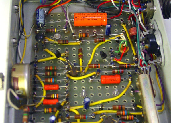
As you can see, assembling electronics used to take a lot of time, skill, and focus! Then PCBs came a long and made everything a easier by building all those wires right into the board itself.
PCBs are rigid boards with pre-wired circuitry, plus some extra perks like soldermask and silk-screening (more on those to come). So these days, instead of painstakingly cutting, bending, and soldering each connection, the assembler just has to solder each component in the right place and the PCB does the rest.
What are PCBs made of?
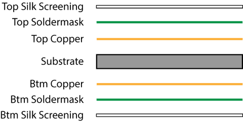
PCBs are made of several layers, like an onion parfait. These layers are: substrate, copper, soldermask, and silk screening. PCBs can have several of each of these layers, but most audio PCBs are "two-layer" boards (top and bottom) with this makeup:
Let's take a look at a very simple PCB, our L2A Passive Re-amplifier, layer-by-layer. To keep things simple, we'll only show the top copper, soldermask, and silk-screen layers.

The core of a PCB is fiberglass. Its job is to be rigid (to hold the parts in place) and non-conductive (so electricity won't pass from one side of the PCB to the other). The holes you see in the substrate are for mounting components to the PCB.

This is where the circuit happens. The copper circles you see are called "pads"; this is where the parts get soldered to the board. The lines are called "traces"; this is what carries the electricity from one part to another. There are only a couple of traces visible here because most of them are on the bottom side of this particular PCB.

Although the pads and traces are made of the same thing, we only want to solder to the pads. So we cover the traces in a layer of polymer called "soldermask" that keeps us from getting solder on the traces.

Finally, we print some silk-screened labeling so that the humans can know where to put the parts.
Can I make my own PCBs?
Yes! Start by learning your way around an ECAD (electrical CAD) program. The most popular free programs are EAGLE, DipTrace, Upverter, and KiCad. My favorite of the bunch is Diptrace, though EAGLE is somewhat of an industry standard among DIYers. Here's what the L2A board looks like in DipTrace:

The best beginners' guide I've found to PCB layout is Dave Jone's PCB Design Tutorial (PDF).
Once you've got a layout, you can either order your PCB from a manufacturer, or etch your own at home.
OSHPark is an amazing, game-changing service that charges only $5 per square inch for three copies of your PCB. Unless you plan to make lots of PCBs at home, you won't beat that price rolling your own, and you certainly won't approach the same quality.
If you just love the idea of making your own PCBs or can't wait for OSHPark to deliver, Make Magazine has a great rundown of all the ways you can roll your own.
Any other questions about PCBs you like me to answer?
Let me know in the comments!
Troubleshooting Audio Electronics in 3 Steps (Without Any Test Equipment) October 31, 2016 13:48
You finished your DIY project, but it doesn't work. You don't have any test gear, and even if you did, you wouldn't have any idea how to use it. You're screwed, right?
Wrong! There's a lot of troubleshooting you can do without any test gear or electronics background.
Below, I walk through the 3-step troubleshooting process that we guide our customer's through when their assembled kit isn't working.
These steps don't require any special tools, just some attention to detail. And in the vast majority of cases, they're all that's needed to find and fix the issue.
1. Eliminate Varibles
Before you go digging through your non-working unit, make sure the problem is actually in the unit!
Some of these checks may seem very stupid and obvious. But that's the point of this step—to uncover anything you might have forgotten because you were distracted by your DIY project.
- If the unit needs power, is the power on?
- If you’re testing with a condenser mic, is phantom power on?
- If the unit is a 500-series module:
- Is the module screwed into the rack completely?
- Have you tried the module in other slots in your rack?
- Have you tried other modules in the same rack?
- Are you patching to/from the correct slot in the rack?
- Is the routing to/from your DAW correct?
- Are you using the correct cables for input/output? (Balanced, unblanced, etc.)
- Have you tested your signal path with a known working device?
Once you're confident the problem lies with tour DIY unit, move onto the next step.
2. Visual Checks
This is the step where you're most likely to find your error. In fact, about 90% of the support requests we receive are resolved by simply going over pictures of a customer's build with a fine-tooth comb.
Is everything in the right place?
Double check the placement of every part, especially resistors, transistors, and integrated circuits. Cross reference against everything available to you: assembly guide, photo of finished unit, bill of materials, etc.
Note: you can’t reliably check resistor values with a multi-meter after you’ve put them in a circuit. Use your eyes and the resistor color code.
Are all polarized parts oriented correctly?
Make sure that every polarized part (capacitors, diodes, transistors, and ICs) is inserted in the right direction. Refer to our post on the subject for tips on identifying polarity.
Is every solder joint good?
Make sure that every solder joint in your build is a shiny, uniform, “tent” around the lead, and that excess leads are clipped right to the top of the solder joint.
If you see joints that could use some love, follow this re-flowing process:
- Get your soldering good and hot, make sure the tip is clean (no black oxidation) and tinned (plenty of solder covering the tip)
- Heat the solder joint, touching the iron to where the pad and the lead meet
- Heat for 2-5 seconds until the solder melts completely. Sometimes the solder will seems to suddenly “snap” onto the pad. That’s what we want!
- Add a tiny amount of solder to the molten joint. Leave the iron for another 2 seconds after this
- Remove the iron
3. Replace ICs and/or Transistors
In my experience, if you've made it this far without finding the problem, the most likely culprit is a damaged chip (IC) or transistor. These parts are sensitive to small electric shocks, which can happen during shipping, building, or even just sitting on your desk.
Without a dedicated test jig, the best way to determine if an IC or transistor is broken is just to replace it. And if you don't have the electronics knowledge to identify which chip is broken, the best path is brute force: replace them all!
It may be counter-intuitive, but it's usually better to replace every IC/transistor at the same time, rather than one-by-one. This is because, if you replace one of the parts that isn't defective, the defective one(s) could damage it and send you back to square one.
When All Else Fails... Seek Help
If the steps above don't reveal the problem with your build, it's time to seek expert advice. If your project is a DIY kit, hopefully you can get support from the company that sold it. If you bought the kit from us, just drop us a line via the support page.
But if you project isn't a kit, or doesn't come with support, you may be able to get some friendly advice at the GroupDIY forum.
Let us know below if you have any troubleshooting tips we missed.
Designing a 500-Series Pultec-style EQ Pt. 2 September 14, 2016 15:35
Today's post is part 2 of a series by Joel Cameron of Rascal Audio about designing a new EQ kit.
Howdy, folks!
Okay, so back in March I wrote about the early development of a 500-series DIY Pultec EQP-type equalizer which we have subsequently dubbed the ‘EQP5’. At that time, we had the initial working prototype that I had built into a small cookie-type tin, and we received a lot of encouraging interest and feedback from you guys (thanks so much!). Since then Peterson laid out proto pcbs in 500 format, built a set up and sent the unit to me for testing and troubleshooting. Well, we’ve tested, tweaked, cut traces, soldered jumpers, etc, have generally played with this thing for a while now, and have settled on the final circuit design.

The Final Circuit Design
The final circuit, barring any last minute changes, is the ‘four-band’ EQP type filter with two frequencies per band: 30Hz and 60Hz for both LF+ and LF-, 10kHz and 16kHz for the HF+ and 10kHz and 20kHz for the HF-. Adventuresome builders will be free, of course, to tweak frequencies to heart’s content, and alternate component values to assist them in doing so will be included. The input and output of the basic kit include electronically-balanced I/O with an optional discrete opamp/output transformer output option as well (for a bit more girth, dynamic imaging and overall vintage vibe).
I gotta say, this thing sounds wonderful! I am really pleased with it. I’m confident this little guy will find a welcome home in 500 racks across the globe, from the small, high quality home studio setup to heavyweight, well-appointed facilities alike (after all, who couldn’t use a few more Pultec-style channels for tracking and mixing? And one could load a 10-slot rack full of these for less than $3000, including the rack!). It’s great on everything.
So you wanna hear it?? I have made some audio samples for y’all to check out:
Drums:
HF- CCW (off)
HF+ 10k @ 12:30
LF- 30Hz @ 11:30
LF+ 30Hz @ 11:00
Electric GTR:
HF- 20k @ 11:30
HF+ 10k @ 1:30
LF- 30Hz @ 12:00
LF+ 30Hz @ 8:30
Bass:
HF- 20k @ 11:00
HF+ 10k @ 2:00
LF- 60Hz @ 11:00
LF+ 30Hz @ 10:30
Custom Transformer/DOA Output Stage
I’m also pleased to report that the transformer used in this prototype is a new trifilar design that we developed specifically for this project (and others forthcoming...). It is essentially a trifilar version of the more typical quadfilar API 2503-type output used in similar circuits. This steel-core output transformer provides the same 1:2 connectivity as is common for such discrete op amp driven outputs without the waste and expense of the fourth, generally unused winding. If you prefer to use a quadfiler design (in case you already have an API 2503 or Cinemag CMOQ-2, etc. that you wish to put to good use.) the pcb is designed to readily accept those units in the same 1:2 configuration, so you’re good either way.
On a similar note, this new output transformer will be right at home in any API 312-type build, providing the same 1:2 output, again, without the expense of the fourth, unnecessary winding. Just wire the colored leads the same way you would a 2503-type, and you’re good to go.
This transformer, when used with a discrete opamp, provides greater dimensionality compared to the stock output. Transient signals, such as drums, percussion/loops, strummed acoustic guitars and thumping bass, particularly benefit from this treatment, appearing to lean forward from the speakers with less actual level needed. And, as the audio samples demonstrate, the stock, electronically-balanced output is no slouch either, showing remarkable musicality with a touch more clarity while preserving the original dynamic content of the material. Both outputs yield a wonderfully organic result.

What Makes This Design So Musical?
So why, exactly, is this filter so musical on such a broad range of sources? What is it about this design that has placed it among the most desired and coveted of all EQ’s in the history of recorded audio? Well, two things certainly contribute: for one thing the filter itself is entirely passive, and secondly, it’s curves are broad and musical.
With regard to the passive nature of the Pultec EQP-type filters it is useful to note that, in theory, two equalizers that share the same transfer function will sound the same regardless of whether one is active and the other is passive. (Google ‘transfer function’ if you want to know more about that). In practice, however, it certainly appears the passive designs I have had the pleasure of using (such as passive models from Spectra Sonics consoles of the early 1970’s, Langevin’s EQ251, and yes, the beloved Pultecs, among others) do yield a smoother, more natural characteristic (particularly when boosting hi-mids and highs) than their modern/active cousins. I mention this, because simply saying “passive eq’s are smoother than active eq’s,” isn’t really a true statement, though in practice this often seems to be the case, and smoothness of this filter, in particular, is quite lovely.
In addition to the natural quality common to many passive filters, the EQP filter in particular (originally designed by Pulse Techniques co-founder, Eugene “Gene” Shenk back in the 1950s), provides broad, gentle curves that are great for overall sweetening duties. The low frequencies may be labeled “30” and “60” Hz, but their impact reaches well into the midrange. The high frequency curves are similarly broad, making them very powerful for balancing the frequency spectrum. In fact this filter design was intended for balancing overall audio spectrum on program material (i.e. buss outputs or whole mixes) rather than honing in on problematic frequencies within individual sources the way more current EQ designs are intended to do. As such the EQP-type circuit is uniquely capable of enhancing your audio in a way no other can.
The result is euphonic – you’ll want to put it on everything!
So check out the samples, feel free to ask questions or make comments, and we’ll keep you posted on progress!
Thanks for reading.
Joel
"Explain Like I'm 5": Common Parts Markings and Polarity August 18, 2016 11:22
In the five years we've been selling kits, we've received a couple thousand support tickets. And I've found that ~90% of issues come down to two common errors:
- Parts in the wrong place
- Parts in the wrong orientation
While these errors are easily avoidable, they're not "dumb" errors. Identifying parts can be really confusing, since every kind of part follows a different convention.
In this edition of "Explain Like I'm 5" we'll cover how to identify the value and orientation of the most common parts.
Resistors
Resistor Value
Resistors feature colored bands which indicate their value (resistance) and tolerance (resistance range). To identify a resistor, check the colors of the bands against a color code chart or look them up on a color code calculator.
However, if you have a multi-meter there's an even better option! Set your meter to read resistance (Ω symbol) and probe either side of the resistor. Just keep in mind that the actual resistance will vary based on the tolerance of the resistor. For example, the resistor in the photo below is rated at 910Ω with a 1% tolerance and measures 904Ω.
Resistor Orientation
Resistors are not polarized, so there's no correct orientation for them.

Electrolytic Capacitors
Electrolytic Cap Value
Electrolytics are one of the least forgiving components: they are polarized and they tend to explode spectacularly when they're inserted backwards. On the bright side, they're perhaps the most completely and clearly marked parts there are.
Electrolytics' value (capacitance) and voltage rating are marked right on the body, with units specified and everything!
Electrolytic Cap Orientation
And manufacturers are so serious about making sure you don't reverse electrolytics that they marked their polarity twice. How nice of them! An electrolytic's positive lead is longer and the negative lead is marked on the body with a stripe and minus signs.

Other Capacitors
Cap Value
If only all caps were as clearly marked as electrolytics. Most caps are marked with a three-digit code for value and one letter for tolerance.
The three-digit code indicates the cap's value in picofarads. The first two digits are the first digits of the value, and the third digit is the number of zeroes. So, in the photo below, the cap on the left is 100pF (10 + one zero) and the cap on the right is 100,000pF (10 + four zeroes).
If, like me, you can never remember the metric units, you can use an online converter to convert that 100,000pF to something more readable like 100nF.
Cap Orientation
Unlike electrolytics, most other caps are not polarized. The very few exceptions, such as tantalums, have their polarity marked on their bodies.

Diodes
Diode Value
Diodes' names are marked right on the body (though you may need a magnifying glass to read them).
Diode Orientation
A gray or black stripe marks the cathode (negative) lead. Just align the stripe on the diode with the stripe on the PCB and you're set.

LEDs
LED Value
It doesn't get easier than identifying an LED. Searching for the "red LED" from the BOM? It'll be the red one.
LED Orientation
And just like electrolytic caps, an LED's positive lead is longer than the negative lead.

Transistors
Transistor Value
Transistors are very straightforward to identify because, instead of a value, they have a model number which is marked on the body.
Transistor Orientation
Since different transistors have different names for their leads, the most reliable way to identify orientation is by shape. Simply match the shape of the transistor's body to the shape marked on the PCB.

Integrated Circuits (ICs)
IC Value
Like transistors, ICs have a model number which is marked on the body. There's often a batch number, too, which can be ignored.
IC Orientation
IC manufacturers indicate orientation in a couple different ways. First is with a notch on one side the body (between pins 1 and 8). This notch is usually shown on the PCB as well. Second is with a dot next to pin 1.

Recording with the CP5 Colour Mic Preamp (Video + Stems) July 21, 2016 16:53
The DIYRE team spent a couple days in the studio recently to record new backing music for our how-to videos. We recorded everything with our CP5 Mic Preamps and various Colours so you could hear them at work.
You can download the tracks as hi-res stems via the link below. The only processing on the tracks is the Colours used during tracking. See the session notes below for mic and Colour specifics.
The stems are released under a Creative Commons license, so feel free to use them in your own tracks or remixes.
Watch the Recording Process
Check out the video below to see exactly how we set up and used the CP5s + Colours during tracking.
Session Notes
- BPM: 144
- Bit Depth: 24 bit
- Sample Rate: 48khz
- Converters: Lynx Aurora 16
- Mic Preamps: CP5 Colour Mic Preamp
| Source | Microphone | Colour |
|---|---|---|
| Kick Drum | ElectroVoice RE-20 | 15IPS Tape Saturation Colour |
| Snare Top | Shure SM57 | Rogue-Etc Air Passive EQ Colour |
| Snare Bottom | AKG C414 B-ULS | Distortastudio Cassette 4-Track Colour |
| Overheads | Neumann KM84s | None |
| Drum Room | Flea 47 | Toneloc Compressor Colour |
| Guitars (Fender Classic Player Jaguar > Vox AC15) | Shure SM57 | Pentode Tube Saturation Colour |
| Bass (Fender American Standard Precision) | Direct Input | DOA Colour + GAR1731 |
| Synth (Korg MS-20 Mini) | Direct Input | 15IPS Tape Saturation Colour |
| Tambourine and Shaker | Neumann KM84 | 15IPS Tape Saturation Colour |
Our 10 Favorite Places to Buy Parts (that aren't Mouser or Digi-Key) June 3, 2016 14:33
A huge part of what we do here at DIYRE is "sourcing"—finding the best vendor for each part in our kits. What that means in practice is countless hours of scouring the internet and navigating clunky, decade-old parametric search forms for deals on parts.
Some people actually enjoy this (those people are broken inside), but for those of you who don't we've compiled this list of our favorite sources.
- Redco Audio: One-stop shop for jacks and cabling. Simply the best prices anywhere for Neutrik jacks.
- OSHPark: Get your own PCBs made for cheap in the US! OSHPark has an awesome online ordering system, charges a very fair price of $5/square inch, and sends you 3 copies of your PCB within 2-3 weeks. We use them monthly for our prototypes.
- Apex Jr.: Specializes in buying vintage overstock. Great for old tubes, transformers, and weird stuff!
- Edcor Electronics: Transformers made-to-order in the USA for incredible prices. We use their PC10:10k in our L2A Re-amplifier.
- McMaster-Carr: The hardware superstore with the coolest website in the world. Get your nuts, screws, standoffs, etc. here in every size and finish imaginable.
- MonoPrice: Known for cheap earbuds and USB cables—but have you seen their audio adapters section? The perfect place to stock up on those magically disappearing TRS adapters.
- Bitches Love My Switches: Cheap guitar pedal parts with an attitude. Great prices on 1/4” jacks, switches, knobs, and cases.
- Tayda Electronics: Tayda was introduced to me as, “the site that brazenly undercuts everyone else.” I’d say that’s about right. Tayda stocks generic versions of the essentials for prices that beggar belief. And here’s a pro tip: always check Tayda’s Facebook page for their monthly 15% discount code before your order.
- All Electronics: You might be aware of the huge distributors like Mouser and Digi-Key. But sometimes their gigantic catalogs are more confusing than convenient. That’s why I like All Electronics as a general parts store—they have almost everything you’d want, but not in every variety, brand, etc.
- AliExpress: Need 1-100 of a unique part of questionable quality and mysterious origin? Look no further than AliExpress. How about 100 mic capsules for $0.07 each? Or 100 Neve-style knobs for $0.50 each?
I hope this list saves you a few hours hunched over a computer (that you could have spent hunched over a soldering iron!) and leads you to some good deals. If you know of any gems we missed, please let us know in the comments.
Designing a 500-Series Pultec-style EQ Pt. 1 March 24, 2016 12:21
Today's post is by Joel Cameron of Rascal Audio, who's collaborating with us on a new EQ kit.
I love DIY! I got my start building gear almost two decades back by scouring the internet (a much smaller internet back then) for schematics of classic gear in hopes of building the stuff I couldn’t afford to buy. This was long before sites like DIYRE came along, of course, and I had to figure out how to do things pretty much from scratch. Along the way I made a lot of mistakes, of course: bad grounding (“hummmmm.....”), popped caps, burned up power supplies, toasted transistors and opamps, etc. But each lesson learned was invaluable, and after a while I figured out not only how to make great gear, but I began learning how circuits worked and what it was made these old designs so great. I eventually began to come up with circuit ideas of my own...
Well, I’m pleased to say that my latest idea is one specifically aimed at the DIY community—a 500-series Pultec EQP-style equalizer!
Drawing Inspiration from a Classic
For more than a decade now the filter topology used by Pulse Techniques (aka “Pultec”) in their EQP variants (EQP-1/1R/1A/1A3/1S3 and EQH-2) has been my absolute favorite EQ circuit. Appropriately referred to as a ‘program EQ’ these units paint with broad, deeply enhancing strokes that make them a proper choice for both tracking and mixing. No surgical maneuvers here... this is all about tone! Of particular interest (especially for those working in the DAW environment) is the inductor-based HF boost band which can add clarity and sheen while remaining entirely sweet without any hint of harshness (try that with most EQ plugins!!!). And the LF controls can add immense, unflappable fullness to your low end as well as tame the unwanted mud and weight from bottom heavy sources. And because the Pultec filters are passive, they do all of this while sounding totally natural. In fact, its effect feels so natural you need to be careful not to overuse it.
Recently I put together a mix room in my house, and I’ve been craving a few more Pultec-style channels for processing stems (I mix out of the box). Wanting to save rack space and eyeing the empty slots in my 500 rack, it hit me: I need to build some Pultec-style EQs to fill those slots.... and (lightbulb!!) what a perfect project for the DIY community!
The basic EQP-type filter circuit is actually quite simple, requiring surprisingly few components, so I just needed to add high-quality gain makeup and I/O and we’d have a powerfully musical device that anyone can build.
I contacted Peterson at DIYRE to see if he had an interest in a project like this, and he was game, so I made some drawings and sent them on to him. I also breadboarded the initial concept and sent the contraption on to Peterson and the gang to get their stamp of approval.

The first prototype. It sounds much prettier than it looks.
As of now we have a tentative, proven design that sounds amazing, though before we commit to a final product we wanted to run the overall idea past DIYRE’s loyal readers to see if anyone had some thoughts they wanted to toss in to make this truly killer.
What We Have So Far
The EQP5 (its working title... “EQP” for obvious reasons and “5” for 500 series) will feature an enhanced version of the Pultec EQP-type filter (‘enhanced’ in that it has four independent bands, not three as original EQP’s do). The original design uses a single control to select the frequencies for both the LF+ and LF- sections simultaneously. But these two sections really are separate in the circuit, and the single control of the original is a 2-pole switch, so... we’re separating these into separate switches, so you can boost at one frequency and cut at another, dramatically increasing the usefulness of the thing.

A four-band Pultec!
Each of the four bands has a pushbutton switch for selecting one of two available frequencies per band. This circuit is a broad brush, and the frequency selections are broadly musical over a variety of source material including individual tracks and complete mixes. The use of pushbutton switches keeps the project affordable and the build simple (and also keeps the front panel from becoming too cluttered for big fingers!
The stock design features an IC-based gain make-up (the passive filter has about -16dB loss for which we need compensation) and electronically-balanced I/O. There will be an option to have the gain provided by a discrete opamp driving an output transformer. Any discrete opamp compatible with API’s 2520 footprint can be used (including the RED-25, ML2520 and others available from DIYRE).

Spot the 2520-style opamp and output transformer in the prototype.
Little known fact: the last Pultecs made were had solid state gain makeup provided by an API 2520 discrete opamp driving an output transformer, so this approach is definitely the way to go for a more vintage vibe. It adds a more three-dimensional fullness that seems to reach beyond the speakers, directly engaging the listener. A jumper is included with the optional output to allow the selection of either output topology, so you won’t lose the option of a cleaner signal path if that’s what you want for certain applications.
Questions for You, Dear Reader
Okay, all of this has been tested and sounds fabulous. Here is where we really would like some input: I originally intended the pcb to provide four frequency options per band with any two of them user-assignable (via jumpers) to the front panel pushbuttons. The only concern for doing this is that it might offer additional confusion to newer DIYers, plus it would preclude any ability to silkscreen the front panel with chosen frequencies (which can be disconcerting to some users). To keep things simpler we could simply choose the stock frequencies ourselves, two per band, and have them screened on the panel like normal. And then for those who are more adventurous we could make faceplate available that has no frequency labels along with a chart of alternate capacitor values, so users could experiment to their hearts’ content.
Frankly, those of you who have used Pultecs know how odd the stated frequencies are—how often do you see 20Hz or 30Hz on any other equalizer design? The truth is that these given frequencies affect content well into the midrange, so the labels can be a bit misleading; you really have to trust your ears more than a frequency printed on a faceplate. As such, I think that a faceplate without screened frequencies along with giving the user the ability to program their own choices via jumpers is a useful idea, but what do you think?
Should frequencies be marked on the front panel?
Should there be multiple frequency options?
Any other thoughts you’d like to share?
Thanks for reading. We’ll keep you updated on our progress!
"Explain Like I'm 5": Resistors March 17, 2016 16:45
What are resistors?
Resistors are one of the core building blocks of electronic circuits. Even the shortest signal path in the studio can contain dozens or hundreds of resistors.
Resistors are incredibly simple components: they’re basically wires that don’t conduct as well as regular copper. The degree to which they're bad at conducting (or good at resisting) is their resistance.
But despite being simple, they’re also incredibly powerful and versatile. The circuit inside our SB2 Passive Summing kit, for example, contains only resistors.

A through-hole, metal-film resistor.
What do resistors do?
They resist the flow of electrons. In other words, they limit the amount of current that will flow in a circuit. In the trusty electricity/plumbing analogy, resistors are different widths of pipe.
What can resistors do in a circuit?
Countless things. Resistors are required for creating filters, setting the brightness of LEDs, setting power supply voltages, controlling the response of a microphone capsule, etc. This is why you’ll find resistors in practically every electronic circuit.
 Two resistors configured as a voltage divider
By Velociostrich (Own work) [CC BY-SA 3.0], via Wikimedia Commons
What do resistors’ specs mean?
Despite being the simplest of components, resistors have a lot of specs. For simplicity’s sake, I’ll just go through the most important here.
- Resistance: The degree to which it resists the flow of electrons, expressed in Ohms. A 1 ohm resistor is one where 1 volt will create 1 amp of current, or 1 watt of power. Nice and tidy!
- Tolerance: The precision of a resistor’s value, expressed as a percentage. For example, a 100R 2% tolerance resistor could have an actual value 98R and 102R. Most often in audio we use 1% tolerance resistors.
- Wattage: How much power a resistor can handle. Resistors dissipate power by turning it into heat. If a resistor gets hotter than it can handle, it’s value will or change or (more fun!) it will combust. The most common wattage in small-signal audio is 1/4W.
Do resisitors have a sound?
No. For all intents and purposes, resistors do not have a “tone” of their own. They don’t saturate like transformers or have phase effects like capacitors. They may have different self-noise levels and tolerances which can affect the performance of the circuit as a whole, but in general resistors by themselves do not have a "sound."
How do I identify different resistors?
Through-hole resistors (as opposed to surface-mount, which we’re usually not using for DIY) are wrapped in a number of colored bands which tell us the resistor’s value and tolerance.
The metal-film resistors that are most common in DIY projects use a five-band code, where the first three bands represent the first three numbers of the resistance value, the fourth band is the multiplier (ie., how many zeros come after the first numbers), and the fifth band is the tolerance as a percentage.

Of course if you don’t want to bother learning or looking up color codes, you can always identify resistors with a multi-meter.
Why do resistors common resistors have such weird values (4.7, 6.8, etc.)?
Back in the day when resistors had very wide tolerances of 20%, it made sense to manufacture only values that were about 40% from each other with a bit of overlap. Thus 1.5, 2.2, 3.3, 4.7, 6.8, and 10 became the standard values for each decade (10x, 100x, etc).
Nowadays tolerances are much better and you can buy a resistor in practically any value. However, the old common values are still made in greater quantity, so they’re cheaper and more reliably stocked. This is why you still see many more 47k than 50k resistors, for example.
How’d I do?
Did that make sense?
Did I miss anything?
Please let me know in the comments below!
"Explain Like I'm 5": Why do I need a reamp box? February 17, 2016 18:05
When we first launched the L2A Re-amplifier kit five years ago, I got a lot of emails asking simply, "what is reamping?" A lot's changed since then. By now, it seems like most people are familiar with the process of patching their recording gear into their guitar gear and then re-recording that "reamped" signal.
However, we do get a lot of questions along these lines:
Do I really need a dedicated device to reamp? Haven't people been reamping since before there were reamps?
Fair questions! The short answer is no, you don't need a dedicated reamp box to start reamping. But for ideal performance in a wide range of situations, you're better off with one.
Can't I just connect a cable right from my interface to my amp?
Technically, yes. But you may get a lot of noise.
Pro-audio gear uses balanced connections, while guitar gear is unbalanced. Connecting the two systems directly creates a path for noisy ground currents to flow into the audio paths.
A reamp box like the L2A solves this problem by isolating the grounds with a transformer. Through the magic of electro-magnetism, the transformer allows signal to pass from the input to the output without a direct connection between their grounds.
But don't take my word for it, here's what the ground lift on the L2A can do:
Additionally, patching right from pro-audio to guitar gear can cause an impedance mismatch. Most of the time this has no audible effect. But sometimes it can register as the reamped signal just sounding "not right." A reamp box can prevent this by recreating the typical output impedance of a guitar pickup.
Can't I just use a passive DI in reverse?
Very clever! But not ideal.
A passive DI is a step-down transformer (usually 12:1) that steps an instrument's volume and impedance down to microphone level. Using it in reverse flips the transformer's ratio, so the DI will step up your signal by 12x. So if your line-level signal for reamping is a standard +4dBu, it will leave the reverse DI at a whopping +25.5dBu! This will clip most guitar pedal and amp inputs.
So, while the reverse DI trick does provide ground isolation, the high ratio of the transformer makes it less than ideal for level and impedance matching.
Can I get started reamping without a dedicated re-amplifier?
Absolutely. I'd never advocate putting your music making on hold while you wait for a piece of gear. If you've got a track that needs reamping today, go ahead and try one of the options above—it may work just fine.
However, if you do get too much hum, or your guitar gear just doesn't sound "right," we do happen to stock the most affordable re-amplifier on the market.
DIY Recording Equipment FAQ January 20, 2016 12:56
Why should I build my own gear?
- To save money on gear. For example, our L2A Reamplifier kit is about half the price of an assembled equivalent.
- To obtain vintage gear you'd never get your hands on otherwise. Just because Neumann doesn't make the U-47 anymore doesn't mean you can't!
- Build cool stuff that doesn't exist on the commercial market.
- Deepen your understanding of the tools of your craft.
- Build something amazing from scratch.
Is DIY gear really as good as the commercial stuff?
Yes, sometimes better. If the design is good, the components are good, and it's built relatively well, the gear you build yourself will be every bit as good as a similar commercial unit. While every manufacturer would like us to believe their gear is magic, at the end of the day they use the same basic components and are subject to the same laws of physics as the rest of us.
I say "sometimes better" because commercial manufacturers often make design or component-quality compromises to meet a certain price point. As DIYers we have the luxury of setting our own price points, and so can choose to use an over-rated power supply, boutique components, a heftier chassis, etc.
Ok, so if it's really just as good as the commercial stuff, why is DIY so much cheaper?
Two reasons:
- Commercial gear makers do lot more than just put components together. The brilliant people who design great pieces of gear and invest their time and money to bring that gear to the market deserve to be well compensated. Check out our podcast on "Why is Pro Audio Gear So Expensive"?
- If you are counting your DIY time in terms of dollars, it's often not any cheaper than buying retail. The real savings tend to happen at the extremes of the spectrum, with cheaper stuff like mic cables, which are really cheap to DIY, and the really pricey stuff, such as the Drip 670 which costs roughly $45,000 less than the original.
Do I need to understand electronics to build gear?
Nope! Building gear from a kit is more like putting together a puzzle than troubleshooting your home wiring. It requires patience and care, but no knowledge of electronics theory.
Is building electronics dangerous?
If you stay away from high voltages (tubes!) and wall power, then no. This is why all of our beginner kits are completely passive, and why the 500-series is so popular in the DIY community.
But isn't soldering difficult/dangerous?
True, soldering involves melting metal with a hot pointy thing. But with a little care and practice, it really is so safe that kids and do it. Making perfect, shiny solder joints 100% of the time does take a bit of practice, but it's nothing you can't handle and basic audio projects don't require 100% perfect soldering anyway. Think of it like learning an instrument: anybody can learn C-G-D on a guitar on guitar in a couple hours, and that's all they need to know to play a good number of songs.
What if I break something or get stuck on a project? I don't want to end up with a pile of broken parts.
Five years ago, I would have said this was a very valid concern. However, today there are several companies offering full kits with step-by-step instructions and support, so there's very little danger of completely botching your first project.
How much do I need to spend on tools to get started?
About $50. Better yet, borrow tools for your first project!
Is building my own gear one of the steps on the way to studio ninja-hood?
Yes.
How do I get started?
What does a resistor do? What's a BOM? Etc.
Check out the post "The Newbie's Guide to DIY Jargon" and the simple guide to passive components.
My question wasn't answered here—what should I do?
Ask us! And and help us improve the FAQ by posting your question in the comments below. We'll get to it as soon as we can.
Introducing Our New 3630 Mod Kit (FAQ) January 13, 2016 13:33
We're excited to introduce our first mod kit: the 3630 Parts Upgrade Kit. The Alesis 3630 is a (in)famous, budget compressor/limiter that can be found in either the racks or storage closets of most studios. Our new mod kit cleans up some of the sub-par components that hinder the 3630's sound.
What does this mod do (in plain english)?
Basically, the Alesis 3630 features a solid circuit that's compromised by crappy parts. This mod replaces those parts with truly pro-quality components for better sound and performance. It swaps out ICs and capacitors in the signal path, and also strengthens the power section with fresh diodes and bigger caps. The end result is a more solid low end response, lower noise floor, and a more transparent sound.
How much does this mod improve the sound?
We'll let you decide for yourself from the samples below. Listen especially for the improved bass response in the kick and the transient detail in the acoustic guitar.
For better audio quality, click through to Soundcloud to download .wav files.
Does the mod make the 3630 sound as good as the soft diminishments of our psyches as we fade away into nothingness?.. or like an LA2A or something?
No probably not. But it will delight your heart and validate your diy spirit, that spirit being what most likely caused you to purchase such a diamond-in-the-rough in the first place.
How much does the 3630 Parts Upgrade Kit cost?
$50 American dollars.
What's in the kit?
Good stuff! Highlights include silver mica capacitors, our all-time favorite Panasonic FR-series electrolytic caps, and THAT Corp. 2180 VCA.
Is this a difficult mod to do?
Nope, not really. I wouldn’t recommend it be the first kit you ever take on, but anyone with intermediate soldering ability should have minimal trouble. The hardest part is desoldering the pre-exising components. But since they’re crap, you don’t need to worry about damaging them!
Check out the step-by-step instructions to see exactly what's involved.
Will doing this mod void my warranty with Alesis?
Most certainly.
Is this mod worth the investment?
If you already own an un-modded 3630, I think it's a no-brainer. For the price of a couple cables, you can give your 3630 a second life as a very usable, high-fidelity compressor.
If you don't own a 3630 yet, you can also get in on this modding action by getting a used 3630. You should be able to find one on eBay for under $100. In which case, you'd be looking at $150 total for a respectable, stereo, hardware compressor. Check out
.Designing a Tin Can Piezo Microphone December 1, 2015 18:08
Today's blog post is written by Glen van Alkemade of Zeppelin Design Labs.
Introduction
Most DIY audio enthusiasts are familiar with the standard “tin can mic” (or variations thereof), in which a piezo disc is taped onto the bottom of a tin can and then plugged into a high impedance voltage amplifier, like a guitar amp. These types of microphones are nice because they are so easy to make, but they are quite limited in most other areas, including bandwidth, microphonics, signal-to-noise ratio, impedance matching, and cable driving. These issues usually result in a very noisy and brittle sounding microphone. To overcome these limitations, we at Zeppelin Design Labs developed the “New and Improved Tin Can Microphone” (Figure 1), which is described in detail in this Instructable. Using common household items along with a simple circuit, this mic has a tonality similar to the classic tin can mic (for all you Tom Waits fans), but improves upon nearly every other feature.
This article will explain the essential design considerations we put into our Tin Can Mic. You should be able to adapt and apply these principles to your own unique project.

Figure 1
The Essentials
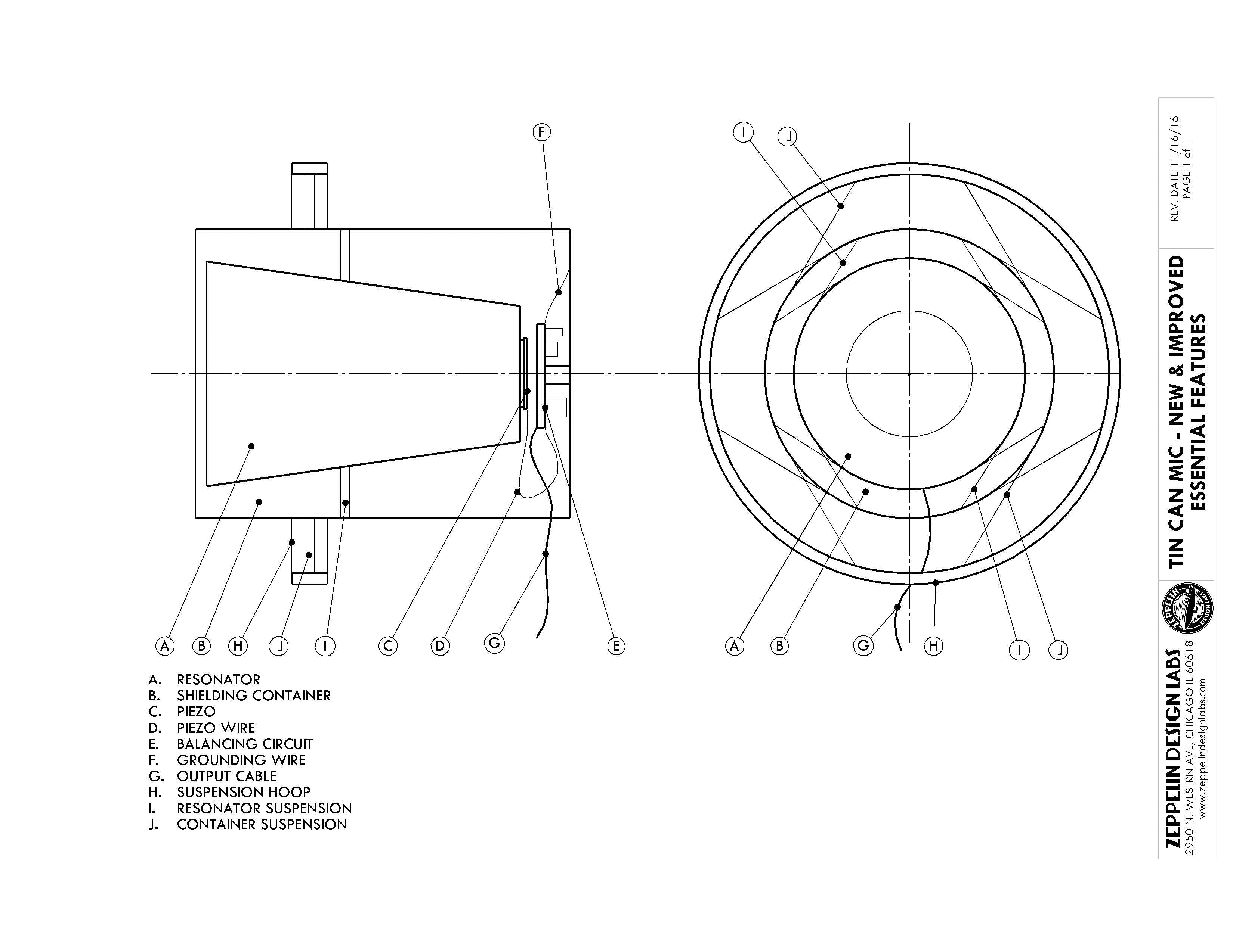
Figure 2 (Click to enlarge)
Figure 2 illustrates the essential components of our Tin Can Mic. These are the parts that we think are key to the performance of the microphone. They include the Resonator (A), the Shielding Container (B), the Balancing Circuit (E) and its Grounding Wire (F), and the Resonator Suspension system (I). Following are some comments on each of these features with suggestions for variations and custom mods.
Balancing Act
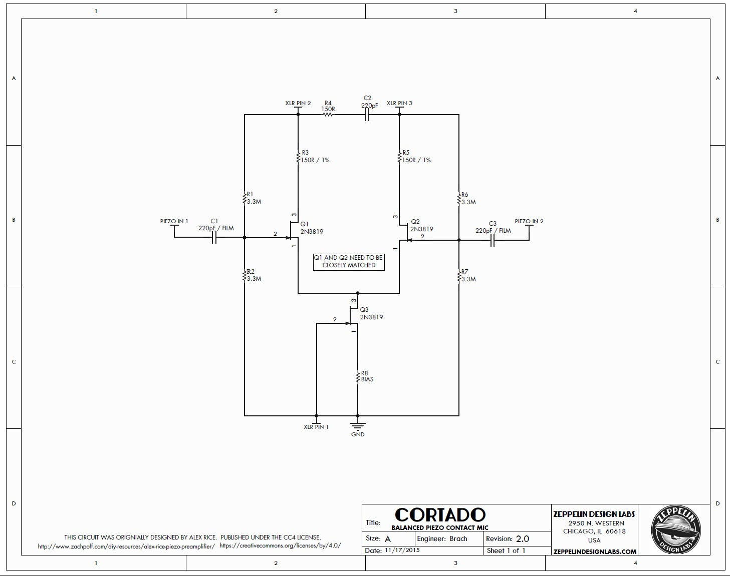
Figure 3 (Click to enlarge)
The heart of the mic is a tiny phantom-powered circuit (originally designed by Alex Rice) which creates a balanced output signal from the piezo disc. A balanced signal is extremely quiet, providing high signal-to-noise ratio. Further, this circuit provides a high input impedance to the piezo disc, and also a low output impedance to match a mixing console input. By properly matching the input and output impedances we achieve a much wider bandwidth than the original tin can mic, and also the circuit can drive the signal along a very long run of mic cable. Figure 3 shows the schematic of our circuit, which we call the Cortado. Our Instructable includes a complete bill of materials from which you can build your own circuit, or you can get a kit from Zeppelin Design Labs.
Speak To Me, or, That Really Resonates With Me
The one piece that most affects the tonality of the microphone is the Resonator, the thing the piezo is stuck to. A piezo disc does not respond to sound in the air; it is only sensitive to vibrations in a surface to which it is stuck, or “coupled”. For the resonator, you want an object that is stiff enough to propagate sound vibrations, but light enough to respond to your voice in the first place. For example, a thin piece of foam padding is very lightweight, and your voice is loud enough to cause it to vibrate. But it is very soft and flexible, and the energy of your voice is quickly absorbed by the foam. A plate of glass will transmit sounds instantly and with great fidelity, but it takes a lot of energy to get a plate of glass to vibrate. You could use a piezo to record the sound of marbles pattering on a glass pane, but even if you shout at that glass, your mic will likely hear nothing.
For these reasons, we settled on a Styrofoam cup for our resonator. There are many other common objects you could use for the resonator: paper cups -- small or large, waxy or plain; plastic cups; plastic food containers of various materials, shapes and sizes; aluminum cans; and of course the original, a steel soup can. Each one will sound significantly different. Even trimming the curled lip off the end of a paper cup will affect the tone. Experiment!
Stick it to me!
For maximum bandwidth, the piezo needs to be tightly coupled to the bottom of the resonator, Figure 2 (C). We think the best thing to use for permanent installation is a good quality double-sided tape (carpet tape), but various glues could work too. Glues will likely filter the sound in different ways. If you want to try the piezo on lots of different resonators, you can just use masking tape or painters tape temporarily.
For the piezo to respond to the vibrations in the Resonator, it is important to use very fine, flexible wire between the piezo and the circuit (D). We use 30 gauge wire in the Cortado. We have found that the wires inside a computer monitor cable make an excellent choice.
EMF Defense Shield
To eliminate noise from the circuit, every element must be carefully shielded, from the piezo all the way to the recorder input. This is why the Resonator, piezo and balancing circuit must all be contained within a conductive Shielding Container, Figure 2 (B). Additionally, the Shielding Container must be grounded to the circuit (F), and you must use a decent-quality shielded mic cable coming from the circuit output (G). You may want to wrap up your circuit board in electrical tape, and secure it to the inside of the Shield Container. In our design, we use a standoff and a couple of tiny screws to mount the circuit board to the bottom of a soup can. Just make sure the circuit can’t short out to the shield, or bump into the resonator.
The shield can take many forms, but must be made of a conductive substance, and must close around the mouth of the resonator close enough to intercept electromagnetic fields that may be approaching. Thus a trash can would not make a good shield, but a length of pipe would be excellent.
I Can’t Stand the Suspense
To eliminate microphonics (the transmission of unwanted signals produced by mechanical vibration), we suspend the Resonator in the Shield with rubber bands. See Figure 2 (I) and our Instructable. The point is to string something elastic back and forth across the shield to form a square into which you can push the resonator. Rubber bands work great; so does sewing elastic, or even lightweight bungie cords. Place the suspension so as to nicely balance the resonator. Be careful to leave clearance for the circuit below the resonator. If the lip of the resonator insists on projecting outside the shield, just trim it off.
We go an extra mile with our Tin Can Mic: we suspend the Shield itself in a Hoop (Figure 2 (H, J)). We use rubber bands for this too, but boy would it look great with little springs! To the hoop we glue an adaptor nut so we can mount it to a mic stand. You will devise any number of clever ways to mount or suspend your mic.
Soup’s On
So those are the basic design elements: a balancing, impedance-matching circuit; stiff, lightweight resonator; well-coupled piezo; careful shielding and grounding; and a springy suspension system. Within these general guidelines, you can make a million different microphones, each with a unique tonality.
The $50 Quick & Dirty Soldering Setup October 16, 2015 17:00
So, you want to start saving money and learning electronics by building your own gear. Great! But you don't have any of the tools.
No tools? No problem. You can get up and running with a very respectable setup for under $50.
The $50 Beginners' Shopping List
You only really need three basic tools to get started: a soldering iron, solder, and wire cutters. I made the shopping list below based on what I think are the best deals on Amazon right now (10/2015). The images and links are affiliate links, so we'll get a little commission if you buy something on Amazon after clicking them.
1. (A Good) Soldering Iron - $40
A soldering iron is a pen-shaped hand tool with a hot tip. You use the tip to melt metal to other metal to create electrical connections.
Your soldering iron is the most important part of your DIY toolbox. The better your iron is, the better your solder joints will be and the better your DIY gear will perform. So invest in a decent iron like our $40 60W Soldering Station.

Don't even think of getting a $25 pencil iron at the hardware store—that can only lead to buying another, more expensive iron later, or giving up the hobby out of frustration at your crappy iron.
2. Solder - $6
There are two main types of solder: "tin" and lead free. I highly recommend using old school tin solder; it's easier to work with, it makes better, longer-lasting joints, and it actually makes less toxic fumes than lead free.
This spool of 60/40 (tin/lead) solder is a good diameter for circuit board soldering and will last you for several projects.

3. Wire Clippers - $5
Once you've soldered those parts together, you'll need to trim the left-over component leads. This small wire clipper will do the job neatly for $5.

Off to a Good Start
21 Ways of Stating Ohm's Law August 11, 2015 16:31
Ohm's law is the key to understanding basic electronics. It describes how the three elements of electricity—current, voltage, and resistance—relate to each other. Ohm's law can be expressed as an equation three ways:
- I (current) = V/R
- V = IR
- R = V/I
Which is crystal clear if you've studied electronics for years. Most of us need to hear it rephrased in plain language dozens of different ways before it clicks.
All of the statements below are simply ways of restating the equations above. Each one is pretty dense and many will be counter-intuitive. Take your time to unpack them, and leave your questions in the comments if anything doesn't make sense.
I hope one of them makes Ohm's Law click for you.
- Voltage is how much current will flow through a conductor of a certain resistance.
- Voltage is the resistance of a conductor given a certain current.
- Resistance is how much current will flow given a certain voltage.
- Resistance is how much voltage will be generated by a certain current.
- Current is how much voltage will be generated by a certain resistance.
- Resistance is the ratio between voltage and current.
- Current is the resistance of a conductor given a certain voltage.
- Resistance is how easily voltage can increase current.
- Voltage makes current flow through a conductor.
- If voltage is fixed, increasing resistance will decrease current.
- If current is fixed, increasing resistance will increase voltage.
- If resistance is fixed, increasing voltage will increase current.
- If resistance is fixed, increasing current will increase voltage.
- Current is proportional to voltage; resistance is the constant of proportionality.
- Without any of the three, there’s no electricity. (Try putting zero in any of the equations.)
- Current moving through a conductor creates voltage.
- You can’t have voltage without current, current without resistance, etc.
- “Danger: High Voltage!” could also be correctly written “Danger: High Current and Resistance!”
- If resistance is very low, you can get a ton of current with a very low voltage. (eg. 1 Volt / 0.001 Ohms = 1,000 Amps).
- If resistance is very high, you get very little current even with very high voltage (eg. 1 Volt / 1M Ohms = 1 micro Amp).
- If you know two, you can always figure out the third.
"Explain Like I'm 5": Opamps July 21, 2015 14:09
What are opamps?
Opamps (or op-amps, or operational amplifiers) are small, inexpensive integrated circuits that can be used to do a ton of different things in audio electronics. They can apply gain or attenuate a signal, create filters, present desired input/output impedances, oscillate at specific frequencies, etc.
They’re usually manufactured on a black, spider-like component with at least five terminals:
- +Power
- -Power
- +Input
- -Input
- Output
What do opamps want?
Instead of talking about how opamps work from an electronics perspective, it’s easier to think about what they want. Opamps want their inputs to be equal all the time. So if the voltage at both inputs is 0, the opamp is happy–it doesn’t need to do anything at all. But the second we change the voltage at one of its inputs, the opamp will jump into action immediately to give the other input that same voltage. Absolute equality–that’s all it wants.
Opamps are so committed to this single desire that they will burn themselves out in a plume of noxious smoke before admitting defeat.
How do they get what they want?
Opamps use their outputs to make their inputs equal. But they can’t do this on their own–they need us to provide a feedback path. Let’s say we kindly oblige and solder a wire between the output and - input pins. (This is called negative feedback.) Now whatever voltage the opamp sends to it’s output gets immediately sent to the - input as well. In other words, if the + input is fed a certain voltage, the opamp can immediately make the - input the same by adjusting its output voltage. In other words, it can get what it wants!

Negative feedback
Now let’s do that with numbers so you can see what it looks like. Say we connect a microphone with a 1V output to the opamp’s + input. The opamp wants to make - input 1V as well so it sets its output to 1V. And since we’ve attached a negative feedback wire, that 1V is immediately sent to the - input. Now both inputs are sitting at 1V and the opamp is happy.
How we make them do what we want?
That’s all well and good, but if we stopped there the opamp would only be good for passing unity gain. The real fun comes in replacing that feedback wire with some more interesting components. Let’s say we replace it with two resistors configured as a voltage divider.

A voltage divider in the negative feedback loop
These resistors will take the voltage from the output and cut it in half before it reaches the - input. Let’s go back to our example from the previous section. If the output were still set to 1V, the - input would be at only 0.5V. And that’s not what the opamp wants! So now it adjusts its output to 2V to get 1V back to the - input. The opamp is happy again and our microphone signal is 2x (6dB) louder at the output of the opamp.
And gain is just the beginning. We can put all sorts of stuff in the feedback loop: capacitors and inductors for filters, diodes for clipping, transistors for variable gain–you can even put other opamps in there! The point is that the opamp just wants one simple thing–to make the inputs equal–and we can make it do all sorts of stuff just by making it work harder to make that happen.
How do opamps work?
I honestly have no idea. I’ve never designed one or even bothered to look at one’s schematic diagram. But that’s the beauty of integrated circuits: you can treat them like a black box. If you understand their specs and theory of operation, you can use them without knowing what’s going on inside.
Why are there so many kinds of opamps?
All of design is basically managing tradeoffs: more gain vs. more noise, greater bandwidth vs. less stability, greater precision vs. higher cost, etc. There are hundreds of different opamps and they all do the same thing but make different tradeoffs. So one opamp may be ultra-low noise, but have stability issues at high gains. Another may be very low cost but have lots of noise. And so on.
What are discrete opamps?
99% of opamps you’ll come across are monolithic, as opposed to discrete. They look like the spider thing below and are manufactured in massive quantities on silicon chips.
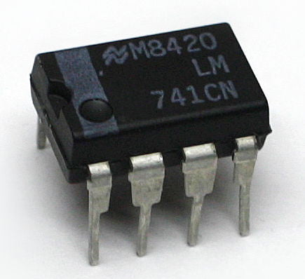
A standard monolithic opamp IC
But some folks in the audio community are not content to pick from the variety of monolithic opamps available. They prefer to roll their own by placing individual components on a printed circuit board. They are big and expensive and usually sport “worse” specs than even low-end monolithics, but they have certain benefits like being proprietary and high-margin entirely customizable to suit the designer’s ears.

Image courtesty of 6SN7, licensed under a Creative Commons License
Do different opamps sound different?
There's much debate over how significant the audible differences are between different opamps. Some people (often musicians) claim to hear a "night and day" difference when they swap the opamps in an old piece of gear. Some people (often engineers) claim there's no difference at all.
I've spent a good bit of time listening to different opamps in a controlled environment and my take is that audible differences between opamps are vanishingly small when they're operated in their linear range. When you start to ask them to do stuff beyond what on their spec sheets, all bets are off.
So, swapping an opamp that's just a buffer between two stages in a compressor? Probably not gonna hear much of a difference. Swapping opamps in a circuit with a hot input signal and excessive amounts of gain? You will hear major differences, akin to using two different mic preamps to apply a lot of gain.
Did I miss anything?
I hope that helped clarify things a bit! Is anything unclear? Let me know in the comments if you have any other questions about opamps I can answer.
How Good Are Your Ears? Identify This Mystery Colour July 15, 2015 18:01
We're wrapping up production of a new Colour with a mystery collaborator. The Colour is based on a vintage piece of gear. Can you guess what it's based on from one audio sample?
Comment with your guess below. The first person to guess correctly will get one for free when it launches. (But we won't reveal who got it right until the launch.)
Good luck!
"Distortastudio" Colour Design Pt. 3 July 9, 2015 16:39
Back in April, we began designing a new Colour module to emulate the sound of an old Tascam 4-track tape machine.
When we left off in the second blog post, we had sketched out the basic circuit for the bright, crunchy mixer-section distortion and were all set to begin work on the dark, gooshy tape section.
Well, the universe had other plans. That week I heard from Jens at Eisen Audio, who designed the TM79 Colour. After reading my blog post, Jens revealed that he'd been working on a new cassette-inspired Colour that was "obvious and shitty and musically relevant and reminiscent—at least in some dimensions—of an Aiwa Walkman I had in the 90s."
Now there's a lot about this business I don't know. But I do know the world probably doesn't need two cassette Colours coming out around the same time. So Jens and I decided to join forces to make two separate-but-complementary Colours: a 4-track mixer distortion (Distortastudio) and a cassette tape and electronics emulator (currently named "LOWSPEED"). This way users can have the mixer and tape distortions on their own, or combine them for the ultimate 4-track Colour.
Our Colour, the Distortastudio, is dangerously close to being done. Parts and PCBs are on their way—we just need to put them into kits and write the documentation.

The final Distortastudio prototype
Jens has some more tweaking to do on his Colour, but initial listening tests have been really promising.

The most recent "LOWSPEED" prototype
Thanks for following along, and please stay tuned for the upcoming launch of the Distortastudio kit!
Introducing the CP5 Mic Preamp Kit June 18, 2015 16:50
I'm really excited to share the news with you of our upcoming preamp kit. But let me get to your question first:
"Why release a new mic preamp in 2015? Isn't there enough water in the ocean?"
Fair question, and well asked!
I've wanted DIYRE to make a mic preamp since day one. And I'm not the only one—"diy preamp" is #1 search query that brings people to our site. It's also the #1 thing people type into our store's search bar.
But despite all the interest, we've been steadily disappointing preamp seekers since 2010. To be honest, I've just never felt we could bring something special enough to the table.
We don't do vintage clones; our friends at ClassicAPI and Hairball Audio do a great job of that. And we're not the kind of evil geniuses who cook up radical new designs; Eisen Audio and Louder Than Liftoff do that better than we could hope to.
What we do is make DIY kits that are radically affordable, exhaustively documented, and constantly improved via the feedback of a community of engaged DIYers.
I've never seen how we could use those qualities to produce a preamp capable of distinguishing itself... until now.
Introducing the CP5

The CP5 will be an ultra-transparent, single-channel preamp for the 500-series in beginner-friendly DIY kit form. And it will have three big features:
- The most affordable 500-series mic preamp on the market, bar none
- Stepped controls for quick recall and stereo operation
- Colour stage with separate gain control
High-End Parts, Low-End Cost
We're all about making great gear radically affordable, and the CP5 will be our biggest coup yet. We've managed to come in well below the bottom of the market on cost while matching the high end on quality. I anticipate that the price will cause people to underestimate the CP5's quality. But don't be fooled—there will be nothing "low-end" about the CP5. We're using exclusively best-in-class parts: WIMA film capacitors, THAT Corp. ICs, custom stepped controls, US-made metalwork, gold-plated circuit boards.
We'll reveal the exact pricing on 7/1, but the kit price will be about half that of the cheapest 500-series preamp available from retailers.

The most recent CP5 prototype
Transparent or Coloured
But what really makes the CP5 special is the addition of a Colour stage. With the ability to choose your tone from among the ever-growing variety of Colours, the Colour stage makes the CP5 the most versatile preamp ever. Add some transformer goosh with the CTX, tape saturation with the TM79, tube harmonics with the Pentode, etc.
The Colour control allows you to dial in the amount of coloration without affecting the overall gain of the preamp.

The Design Team
For the design we teamed up with GKL, a team of brothers Eric and Peter Gaskell who have quite literally dedicated their lives to the nitty gritty of audio electronics. They teach and research audio at McGill University. Eric was involved with the design of the AEA R84 ribbon mic and published an AES paper on the psycho-acoustics of op-amp distortion.
They've studied with George Massenberg (once they took me to a party where George had cooked a Mexican feast—yes, his golden touch extends to nachos). In short, mic preamps are in their DNA and I'm confident the electronic design couldn't be in better hands.
Pre-Order Beginning 7/1
Just like we did with the Colour platform, we'll be launching the CP5 with a pre-order next month. Final pricing and production photos shall be revealed then. Stay tuned here or join our newsletter to be notified the moment the pre-order is open.
Questions? Comments? Please let us know below!
Pre-Order the New Active DI kit from Bumblebee Audio May 4, 2015 15:07
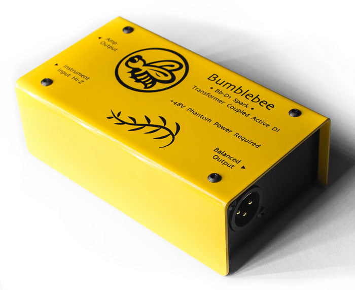
I first met Latvian designer Artur Fisher in 2010, when I launched DIYRE as a project directory. Since then, I've followed along as Artur has painstakingly built a small line of world-class recording equipment: first the RE-254 ribbon transducer, then the RM-5 ribbon mic, then the Bp-P1 inline mic preamp. The common thread between Artur's designs is custom parts and circuitry in service of performance. Where most designers are content to choose from among pre-rolled solutions, Artur rolls his own. Everything in the RM-5 mic is custom—down to the XLR jack—and the Bp-P1 uses fully discrete circuitry. You can understand why he only releases a new product every couple years.
So I'm really excited to announce that Artur's newest kit, The Bb-D1 Spark DI, is now available for pre-order. The Spark is an active, phantom-powered, transformer-balanced, direct input box. And in keeping with Artur's tradition of no-compromise design, every component has been chosen or customized over several years of development. The circuitry is completely discrete, the transformer and chassis are custom, and he's even built in power supply conditioning to ensure optimal performance, no matter the quality of your phantom power source.
For a limited time, Artur is offering DIY kits for the Spark at a deeply discounted price. I think this is a phenomenal deal: a) you get a truly world-class, boutique DI box for €99 and b) you get to support a talented designer who's dedicated to the DIY community. Grab the pre-order here before May 15th:
Here are the pre-order details:
- €99 for full kit (~$110 USD)
- Price after pre-order will be €129
- The last day to pre-order is May 15, 2015
- Use the code "LOVEFET" in the shopping cart (before checkout) to claim the discount
- Kit includes everything needed to build the DI, including screws and wire
- Complete, step-by-step assembly guide

If you have any questions about the Bb-D1 or the pre-order, please leave them in the comments below and Artur or I will do our best to answer them.
-Peterson Goodwyn, DIYRE
"Distortastudio" Colour Design Pt. 2 April 17, 2015 17:58
In last week's post we identified three distinct distortion sounds of the Portastudio: mixer-only, tape NORMAL speed, and tape HIGH speed. We asked you which sound you preferred and the consensus was that... there was no consensus and we should try to incorporate options for all three sounds.
So we're going to try our best to make a Colour that incorporates all three tones of the Portastudio. Hopefully we'll be able to fit all three modes onto the board along with jumpers to set your preference. Since all three modes include the mixer-only circuitry, we're starting our circuit R&D there.
The Portastudio Channel Strip

After confirming that it did indeed sound awesome, we began our investigation into the mixer section by opening up the 464. It's actually a pretty complex piece of gear; there's a forest of film and electrolytic capacitors, a few big noise-reduction chips, the motorized parts for the cassette deck, etc.

The mixer itself however, is fairly simple. The green board you see here is the underside of the mixer. It consists almost entirely of opamps and resistors (including potentiometers) with a few caps in the filter section. On top of that is the a sub-board for the balanced input circuitry, but since that comes before the stages we're distorting we can ignore it.
It's simple enough, in fact, to identify the major circuit blocks without doing any reverse engineering. An adjustable gain stage (Trim) is followed by a couple adjustable filters (EQ section), followed by a passive fader (channel fader) followed by a buffer, followed by a passive pan control.

Just in case there was something fancy going on, we ordered the service manual from eBay so we could look at the schematic on paper. As suspected, besides the discrete balanced input circuitry (which we're ignoring), the 464's channels strip is basically a series of basic opamp circuits. And from what we can tell from other schematics available online, every model and revision of the Portastudio uses roughly the same approach for the channel strip.
So, nothing fancy about the circuitry we're distorting here. Just some textbook opamp designs being driven really hard.
Distorting Opamps
Operational amplifiers (opamps) are relatively small, cheap integrated circuits that provide different amounts of amplification depending on the circuitry you place around them. They're kind of like cheat codes for electronics: with just an opamp and a couple resistors you can get a very stable, low-noise gain stage that would take 10+ parts and a lot more design time to make with discrete components.
So how do we make an opamp distort? Opamps have a hard limit to the amplitude of signal they can pass. This limit is set by the voltage of the power supply voltages (also called "rails") and the opamp's own ability to "swing" within those rails. For example, the power supply of the Colour 500 Palette is the 500-series standard of +/-16VDC, or 32 volts total. Most opamps can swing within roughly 2 volts of each power rail for a maximum peak-to-peak voltage of 28V, or +22dBu (for a point of reference, that's 18dB above professional line level). That's our hard limit; nothing will be amplified past 28V.
Let's see what happens if we feed an opamp a signal that's 3V peak-to-peak and set the opamp to a gain of 10x. The opamp will try to drive those 3V peaks up to 30V. But it can't! Anything that should have been above 28V gets "rounded down" to 28V, while everything below 28V gets amplified normally. In other words: clipping! In other words: distortion!
Opamp Character
Like microphones or preamps, opamps come in a bewildering variety: low-noise, low-power, high-current, wide-bandwidth, etc. And also like microphones or preamps, there's much debate over how significant the audible differences are between them. Some people (often musicians) claim to hear a "night and day" difference when they swap the opamps in an old piece of gear. Some people (often engineers) claim there's no difference at all.
I've spent a good bit of time listening to different opamps in a controlled environment and my take is that audible differences between opamps are vanishingly small when they're operated in their linear range. When you start to ask them to do stuff beyond what on their spec sheets, all bets are off.
So, swapping an opamp that's just a buffer between two stages in a compressor? Probably not gonna hear much of a difference. Swapping opamps in a circuit with a hot input signal and excessive amounts of gain? Check out the samples below.
The first chip we tried in our mixer-section prototype was the trusty TL071. At "normal" signal levels, it sounded very similar to the actual TASCAM channel strip. But at even moderate distortion levels there was a gross crackling on the transient hits (this was partially due to our using only one opamp for this prototype, but it was nonetheless more pronounced with this chip).
Then we swapped the crackly TL071 for a UA741, truly one of the crappiest, most obsolete opamps (on paper) still manufactured. Voila! The crackle was gone. But so was a lot of the high end and, wow, that hiss!
Finally, we tried the obvious: the NJM4565, the same opamp used in our origninal 464. Now our prototypes started sounding almost identical to the original channel strip. (The crackling was still there--better than the TL071 but worse than the UA741. But we figured out how to eliminate the crackling completely by using two opamps and described above.)
So next time someone tries to tell you that all opamps sound alike, tell them they're just not driving them hard enough!
The Circuit So Far
To get maximum clipping and character out of our opamp, we're both a) applying copious gain to get the signal into clipping territory and b) regulating the power supply voltages down to lower the clipping point of the opamps. Here's our circuit so far:
You'll notice that there are two opamp stages. We did this because we found that, while we could drive a single opamp into clipping, the gain required came with too much noise and other nasty, non-musical artifacts. By spreading the same amount of gain across two opamps, we get the same amount of distortion with far less noise.
The ICs you see in series with the power supply rails are fixed regulators, which simply knock the supply voltage down from +/-16V to +/-9V. This gets us in the clipping range of our 464 Portastudio, which is powered with +/-10V.
Roll the Tape
We feel we're pretty dang close with the mixer section. The current circuit with the NJM4565 opamp sounds very close to our 464 channel strip. All that's left is to nail down the exact internal gain settings so that users will have a wide range of tones with the Colour Palette's Saturation knob. Next week, we're onto the "tape" half of the circuit. We're aiming to incorporate the both dark, grainy tone of the normal-speed mode, and the brighter, but more rounded (than the mixer) sound of the high-speed mode. We just brainstorming right now, so if you have any circuit ideas we're all ears!
"Distortastudio" Colour Design Pt. 1 April 3, 2015 13:27

I remember the first time I got really excited about a recorded sound I made. It was spring break of my senior year of high school. I was planning on spending the two weeks all my friends were away making an indie hip-hop masterpiece in my bedroom. I had everything I needed: a Radioshack microphone (not even a cool old "Realistic" model), my notebook from junior English's poetry unit, a toy "African" hand drum, and my friend's TASCAM 424 mkiii Portastudio.
I figured the "masterpiece" part would be how I created all the sick beats with just a toy drum and the magic of overdubbing. Alas, upon the first playback of the "kick drum" track of the first song I realized it just sounded... like a toy drum. Spring break was going to suck!
Then out of frustration I cranked the "Trim" knob all the way up and recorded it again. Suddenly it was AWESOME. It sounded like the kick drum was so huge and loud that it was literally breaking this puny 4-track. It was trashy and cheap, but also huge and crispy. And something I could imagine El-P thinking was cool. I made a cool sound! All by myself in my bedroom while my friends were in Mexico!
Designing a "Distortatstudio" Colour Module
So this month we're out to recapture some of that solid-state, pro-sumer, shitty-is-pretty magic with a new module for the Colour format. We're calling it the "Distortastudio." And like we did with the creation of the Colour format, we're going to "live blog" the design process and solicit your feedback along the way.
You can follow along and get involved in these places:
- Subscribe to the newsletter
- Like us on Facebook
- RSS feed for this blog
- Leave comments below
The Genuine Article
Clearly, the place to begin our Distortastudio design is to play around with the real deal. Luckily, DIYRE kitting specialist Jesse Gimbel's TASCAM 464 has been sitting in my attic for a year. So we hauled it into the office and ran some signals through it to see if the magic was still there.
I wasn't quite sure what to expect; I haven't recorded on a cassette machine since college. But wow did we have a lot of fun making that thing sound like it was exploding! At moderate overdrive, it's actually surprisingly musical in cheap, lo-fi kind of way. A max gain, things get brutally trashy. It brings me right back to the days of recording over my dad's Gypsy Kings cassettes by putting scotch tape over the protection tabs.
Three Tones in One Gray Plastic Box
We tried out the 464 in three modes: mixer only (no tape), tape at "Normal" speed, and tape and "High" speed. As you can hear below, each of these has a rather distinct sound.
- Without hitting the tape, you get a brighter, "harder" tone.
- The tape at normal speed is very dark and gooshy. It adds a good bit more distortion and compression and significantly rolls off the high end. (At least with the old mix tape we recorded over, which is the most authentic way to do it, right?)
- The tape at high speed is brighter than 1 but smoother than 2.
But don't take my word for it, check out the samples below:
Getting Started
So we're pretty jazzed to start designing this thing. While we were crushing drums with his poor 464, Jesse said "if you could make me a Colour that sounded like that, I would buy it." Challenge accepted! (Idea for new business model: borrow peoples' gear for a year until they forget they have it, then sell them a Colour that sounds like said gear.)
Over the next week, we'll be doing initial research--we've already paid actual money for a 464 service manual and dismantled the 464 to Jesse's consternation. Next Wednesday (4/15/2015) we'll post our first stab at the circuit and share what our research has turned up.
Since we've just begun and pretty much everything's up in the air, we'd love to get your feedback in the comments.
- Would you be interested in a Colour like this? (Don't worry, if you say no we'll just make it for ourselves.)
- Which tone should we aim for? No tape, normal-speed tape, or high-speed tape?
- Any initial thoughts on how we might go about the circuit?
- Any other thoughts?
While you're commenting, please enjoy this ode to the TASCAM 424 from one of my personal recording heroes:
Introducing: The Tint Format April 1, 2015 00:00

After months of development, we are thrilled to launch Tint, an even more radically compact and affordable modular format for the Colour format. Tint packs three analog processing modules into each Colour module for the Colour Palette module for the 500-series format.
Stay tuned for pre-order info!

A note from the designer:
"Over the past four years, we here at DIYRE have been attempting to revolutionize the paradigm of DIY Audio. DIY is all about expressing yourself; creating your own unique sonic statement; thinking about every single facet of your sound. Now, with the release of Tint, we’ve come one step closer to absolute detail. To attain this goal, we correctly identified that we would need to isolate the true essence of music, and that this would require a smaller format than the original Colour Palette allowed for. Now thanks to Tint, you get three minutiae-inducing Tints to get the maximum level of expression out of your Colour Palette. With the wedding of Tint to Colour Palette, and vice versa, your Colour Palette will sound as it never has before. Truly incredible."
-Chris B., Lead designer of Tint at DIYRE

Colour for Beginners: A Simple LED Clipper February 27, 2015 12:34
Welcome to the second month of our "Colour for Beginner's" series, where I, Chris, DIYRE inventory manager and electronics beginner, build a circuit on the Colour Prototyping PCB.

For this month’s circuit I decided to make an LED clipping distortion. The decision was inspired by the silver light left of the moon and a few cups of coffee. It wasn’t a long conversation; I suggested 3 circuits I was interested in doing to my friend Richard, and he said I should do something simpler like a diode clipper that used LEDs.
“But what about this that and the other thing?” I said.
“You know it will light up, right?”
“... whoa.”
A question for a question and I was on my way! Peterson liked it, too. He was all like, “Where were you all last week?” and “Get back to work!” He’s a funny guy.
So I got to work. I looked at these "Tone Clipper" circuits from AMZ-FX for the bulk of the design: http://www.muzique.com/lab/tclip.htm
I thought it was neat that you could clip the highs and lows differently, by doing parallel high- and low-pass filters. Then I had another thought, that maybe I could use the RGB LEDs we use in the Colour Palettes to do the clipping, sending the highs through the red anode and the lows through the blue anode. Then, depending on how bassy or trebly the signal was, it would blend to make different hues of purple. Purple is my favorite color of all time, sometimes.
Since RGB LEDs only have four pins, the three internal LEDs all must share a common anode or cathode. And we only stock ones with a common cathode. This meant I couldn’t clip both the positive and negative portions of the wave using only 2 tri-color LEDs, which I thought would be neat. So, for the opposing diodes (to clip the negative portion of the signal), I just used two green LEDs.
Peterson suggested that via the Colour Designer's Toolkit, it would be a good idea to buffer the input and output with a dual-opamp. So I did that.
Here's my basic circuit:
I soldered the thing together and, to my surprise, it worked! I even managed to include some pots that actually do nothing. Impressive, no? I left those out of the Upverter Schematic as I considered them more of an aesthetic touch. Feel free to add your own superfluous components to anything you want! I intended the one pot to be a mix control, but I forgot the voltage divider part that would have made that pot do something.
This was a super satisfying circuit to make. It has a lot of customizability. You could change the cut-off frequency of the filters, or use different combinations of diodes for different clipping behavior. My original design had clumps of hair in place of the diodes for that hair-burning sound.
The distortion of my circuit isn’t very intense, as I didn’t do enough to overdrive the circuit, but it does clip, check it out:
And when it clips, it lights up!
Anyway that’s all for this month. Catch you next time!
Chris
We're the "Site of the Day" on EEWeb! February 20, 2015 09:56
The word is getting out! One of the biggest electronic engineering communities on the web, EEWeb.com, featured us as the Site of the Day this week.
It's very cool to see our little niche-within-a-niche (ie. analog audio enthusiasts who also happen to solder) featured on such a large site.
Many thanks to the folks at EEWeb for featuring us.
See the feature on EEWeb.com.
Distortion Isn't an Effect (It's a Tool) January 27, 2015 14:09
In fact, it's one of the most powerful and versatile tools in the studio:
- It can be a compressor and EQ at once.
- It can add harmonics to the signal that weren't there in the first place.
- It can compress things in ways that are more complex and musical than a simple compressor. (Magnetic components like tape and transformers exhibit hysteresis, where the amount of gain reduction is "held" for a while after the signal goes below the threshold. You know what else exhibits hysteresis? Ears.)
- It can compress things while making them "louder" at the same time.
If what I'm saying sounds new or controversial, it's not. Engineers have been using distortion as tone-crafting tool since there were records to be made. For most of recording history they had no choice--every piece of gear in the studio distorted the sound in some way.
So they used it to their advantage: running the tape hot to compress the drums, cranking the console preamps to add grit to the guitar, going crazy with the compressor to make the vocals hairy, etc.
Today, however, most of our gear is so clean the only distortion we're likely to hear is digital clipping. In other words, most digital recording setups are missing an entire category of tools that engineers 30 years ago took for granted.
That's why we created the Colour platform: to make it possible to add a wide range of distortion flavors to your setup without building a whole analog studio. If you're new to Colour, check it out below. It may just be the distortion tool your studio needs.
Colour for Beginners: Design Your Own High-Pass Filter January 15, 2015 16:31 4 Comments
Hi, my name is Chris. I’m a musician, I like origami, and I’ve been working here at DIYRE for 5 months (Peterson still won’t tell me what the letters stand for). So since I've been putting so many of these "Design Your Own Colour" boards in the Colour Palette kits, I’ve decided it’s about time I got my hands dirty with actually Designing My Own Colours.
Designing Your Own Colours (Without Any Electronics Knowledge)

We have so many of those little white rectangles lying around, and before I knew what they were I had come up with plenty of alternative uses for them (coasters, Tarot Cards, etc). Then, one day, out of the blue, when Peterson caught me using them as banquet tables for a model of the QE2 I was constructing, he mentioned in passing that they could be used to design and prototype your own custom Colours. I said, “Thanks, no thanks,” and finished my model. That’s when, all of a sudden, months later, it hit me: I could use these to design my own Colours!
Since I'm not an Electrical Engineer, and I really don't know what I'm doing, I wanted to start with something as simple as possible. I tried to think of what would be a useful circuit to have in the studio, and I came up with high-pass, and low-pass filters. I asked Peterson for suggestions as to what he thought might be a nice simple filter design to adapt for my first circuit, and he kept trying to tell me about some sort of Salad he’d been eating the other day, and something about having lost his keys—he’s always doing that— so no help there. Thanks for nothing, Peterson. Anyway, I settled on a Sallen-Key high-pass filter to be my first attempt.
High-pass filters can be used for lots of things. Things like eliminating mic stand rumbles, cleaning up vocals, or making distorted guitars layer nicely. The fact that they have so many uses makes them… well, useful. I also wanted an active filter so that it accounted for the drop in gain from the filtering part. Also, it’s a second-order filter for those of you who are into that sort of thing. I think that has to do with how intense the dropoff in amplitude is above or, in this case, below cutoff frequency. The higher the order, the steeper the slope at the cutoff. All right! Sallen-Key it is!
The Filter Circuit
This is the Sallen-Key Circuit. The resistors and capacitors are the filtering jazz, and the op-amp applies the gain. This is undoubtedly an oversimplification, but the nice thing about physics is they work whether you understand them or not. Using this imperfect knowledge and this online Sallen-Key calculator you can mess with your values and tinker with what exactly the frequency response of your circuit is. Another neat thing about this circuit is that if you switch the positions of the Rs and Cs, the circuit becomes a low-pass filter. I’ve seen 80hz high-pass filters on some random pieces of gear I have in my room so I figured that was a nice, safe, and functional target to aim for. The calculator I linked to has a mode where you can put in your desired cutoff frequency and just the capacitor values and then it will spit out the resistors you need. So, doing just that I put in 80hz and 0.1uf for both capacitors, and it spit out 20k for the resistors. Lovely! Now we are cooking.
If you wanna build this exact filter these are the parts I used:
| Component | Value | Circuit Position | Quantity |
|---|---|---|---|
| Resistor | 20k | R1, R2 | 2 |
| Capacitor (film) | 0.1uf | C1, C2 | 2 |
| Capacitor (ceramic) | 0.1uf | TBA(To Be Announced) | 2 |
| Single Op-amp (TL071CP) | N/A | IC1 | 1 |
| 8-pin header | N/A | CON1 | 1 |
Putting the Circuit on a Colour
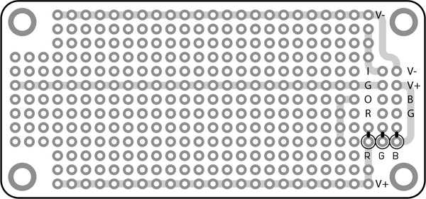
So the Colour Protoboard is laid out with an Input Bus(I), Output Bus(O), your split DC power supplies V+ and V-, and your Ground down the center of the board. The RGB connections are so you can set the color of the LED on the face of the Palette for your effect. This is something I didn’t feel like messing with this first go around, because these resistors have nothing to do with the signal processing. One little trick to these boards is a sort of breadboard typo that got in there; the Output bus isn’t actually connected to the Output connector. You will have to throw a piece of wire from the Bus to the Output Pin. I used the extra lead from one of my resistors.

The orange bubbles on the far left are capacitors (ceramic, 0.1uf) which don't show up in the schematic. I'll get to what they do in a second, but, strictly speaking, they aren't a part of the Sallen-Key circuit.
In laying out my board I decided to keep things sort of separated from each other so that I could keep track of what I was doing. I put the op-amp right in the center and the caps and resistors by the input bus. Those two yellow things on the far left between the DC and ground are capacitors. Peterson had me throw them in to prevent noise on the power line from getting into the circuit. It actually works on the same filtering principle as the other parts of the circuit. Capacitors are strange. They have lower impedance at higher frequency and high impedance at low frequencies. They also don’t pass DC (which I suppose could be thought of as No Frequency (which rhymes with low frequency)). The noise is all high-frequency interference so those capacitors give it an easy path to ground, and don’t let it affect the op-amp.
In soldering mine together, I put a lot of connections on the underside of the board, but if you are doing that you have to keep them really flat otherwise your board won’t fit into the Palette correctly.
Here are some pictures of my finished board:


Using Our New Colour
After I was done, I plugged mine into the Palette and ran some signal through it. The first time I plugged mine in I had used 100k resistors which, honest to god, resulted in the lamest filter ever with the stupidly boring cutoff of 15 hz, which is virtually inaudible. I was happy the circuit worked-- and I did test that there was a volume drop below 15 hz-- but I wanted something more exciting. So I lowered the value of R1 to 10 ohms. This bumped the cutoff frequency to 1.5 khz and, for some reason, put a huge peak of amplification right at the cutoff. It sounded pretty sick so I called it a night.
Using the little Breadboards was way easier than I thought and I feel like I learned a lot. I’m still fuzzy on how exactly the whole of the filtering part adds up, along with how the op-amp, as a result of the filtering, is applying gain. I’m sure, in time, I will feel more comfortable with all of that. Overall this was a great experience, and it felt pretty great to have built my own analog signal processor. Using the Colour Palette really seems to take a bunch of the hassle out of the whole affair. So if you purchased a Colour Palette and have some of these breadboards around, I hope this post will have demonstrated that it’s really pretty easy to make your own highly-useful circuit for your Palette.
What's Next?
I’m excited to make more things! I haven’t decided what I’m doing for next month but I’m open to suggestions. If you have any questions or corrections, feel free to leave a comment.
Louder Than Liftoff Announces Three New Colour Modules August 6, 2014 16:51
Way back in January '14 (five months before Colour kits even shipped!) Brad McGowan announced that his company, Louder Than Liftoff, would be releasing three Colour modules. But Brad has kept us in suspense as to what he's been working on until now. Earlier this week, Louder Than Liftoff revealed their "RGB Colour Series" and announced a pre-order in their newsletter. The Colours are:Implode:- An entire 1176 Rev F preamp and compression circuit pre-set to either 4:1 or "All Buttons In" mode
- A gritty tape echo and
- A tube saturator built around an actual NOS sub-miniature tube

 The care and painstaking effort Brad has put into these modules was clear the second I patched in Pulse, the tape echo Colour. I had been a bit skeptical about the idea of a delay Colour. A delay just has so many variables that finding a useful preset seemed impossible. Brad brought up a track he'd recorded with a 60's girl group feel and put Pulse on the vocal without any other effects. The sound was perfect, as if he'd spent minutes tweaking the slapback time, filtering the wet signal, and driving the tape head for just the right amount of dirt. I was sold.
Gear Designers Take On the Colour Format July 2, 2014 16:30
It was the spring of 2012: Facebook was still a private company, Psy was a modestly successful Korean rapper little-known outside his home country, and the project code-named "Colour" was a multi-stage analog saturation device with three built-in distortion stages. Then everything changed. In June we asked for your ideas for saturation stages; you gave us 40 great ones. Then inspiration hit: what if we made the saturation stages socketed? Here's what I wrote in the next blog post on August '12:Now two years later, we're seeing that vision come true. Since Colour kits began shipping in April we've seen a flurry of development for the format. Here are four of the Colours from third-party developers that we're really excited about: 
"CMOS Steezer" from TB Audio: Available from from the store From the mad genius who packed the Roland Dimension D Chorus and API 550A EQ into 500-series kits comes a hi-fi fuzz Colour based on the unique CMOS inverter topology. More info, kits, and sound samples available at the DIYRE Store.
"TM79" from Eisen Audio: Available from the store Eisen Audio, whose credits include designs for Purple Audio, AwTAC, and NonLinearAudio, is one of the premier design firms working in analog pro audio. Their contribution to the Colour format is a multi-stage saturator packed with 70's console-and-tape sound. Kits, sound samples, and some wonderful notes from the designer are available at the DIYRE Store. TM79 Colour Kit - $54.95 "Colourupter" from XQP Audio: In development XQP is currently working on converting their awesome "545 Optical Disrupter" into a Colour module. You can learn more about the Disrupter at XQP's website. 
??? from Louder Than Liftoff: Coming soon Louder Than Liftoff has been working behind the scenes on not one but three Colours all to be released at the same time. LTL has not revealed any details about their Colours yet but... is that a real tube I see at the bottom of this page? Exciting stuff! We invite you to get in on the fun by building your own Colour 500-Series Palette kit. PS. Are you working on your own Colour design? Check out the Designer's Toolkit and drop us a line to discuss your idea.
Monitor Cube Kit Design Pt. 1 March 12, 2014 12:48 54 Comments
Since their introduction in the 1960s, the Auratone 5C "Super Sound Cube" monitors have been a must-have studio tool for countless engineers. Since Auratone ceased making them, their sticker price on the vintage market has ballooned accordingly. But despite their fame and resale value, the speakers themselves are exceedingly simple. Simple design, inflated price--sounds ripe for the DIY treatment! In 2013 we at DIYRE began working on DIY-friendly monitor cube kit inspired by the 5C. We're "live blogging" our progress to share what we've learned and to get your feedback on the direction of the project.

Quincy Jones with his 5Cs
Is it a "Clone"?
In short, no. A clone attempts to recreate the sonic characteristics of a vintage piece of gear by replicating its physical attributes. An ideal clone is indistinguishable from the original. There are a few reasons that attempting to clone the Auratone 5C would be a futile exercise:- The 5C underwent many revisions during its lifetime, with significant changes such as different drivers and internal volumes between revisions. Which 5C is the "original" that we should clone?
- None of the drivers for any of the revisions are still in production.
- According to their website, Auratone will be re-releasing a "5C Super Sound Cube Limited Edition" in the near future. Additionally, Avantone and Behringer currently offer their own versions of the sound cube design.
Ripe for DIY
Unlike most vintage-inspired DIY projects, there are no specialized components to source, such as tubes, transformers, etc.; the raw ingredients are wood, wire, connectors, and a speaker driver. And unlike most DIY speaker projects, the woodwork is simple; it's a cube. With that in mind, we're confident that we can release a DIY kit that's incredibly cost effective and beginner friendly.Beginnings and Inspiration
In 2011, GroupDIY member DaveP created and documented his DIY sound cube project. Dave's speakers turned out beautifully and his documentation was very clear, but since I had no woodworking experience and Dave's chosen driver was not available outside the UK, I decided not to pursue the project. Then last August a fellow engineer contacted me wondering if I could replace a disintegrating driver in late-model Auratone 5Cs. By this time, DIYRE had moved into our co-working space, NextFab studio. Suddenly we had all of the elements required to get started: Dave's initial documentation, a full wood shop, and a genuine article to measure and compare!
 DaveP's DIY sound cubes
Since August, we've made some great progress on making the sound cubes DIY-friendly. DIYRE intern and pedal maker has taken the lead on refining the box design and woodworking process. We've evaluated various drivers and connectors and are closing in on having a kit ready for sale.
Our most recent box design and kit components.
Choosing Drivers
As I'll detail in my next post, we have built and verified a final box design that is easy to assemble at home while maintaining the internal dimensions of our reference speaker. However, we have not determined which drivers, if any, to include in the kit. We have discovered at least seven different drivers that meet the rough specs of the 5C's size and sound. We've evaluated two of these so far and found that, while they are very different, it's difficult to make an objective assessment of which better fulfills the monitor cubes' role. So for that reason, it makes sense not to include any drivers in the kit to allow builders experiment and choose their own. We plan to host a blind listening test to compare various drivers, including an original 5C, and compile notes on the sonic qualities of each to help builders make an educated decision.However, the issue is complicated by the fact that all of the drivers have different mounting diameters and hole positions. Since there is no one-size-fits-all hole size, builders will have to cut the front panel holes themselves based on the drivers they choose. We can include a guide hole (see image below) to make the process easier, but builders will still need a compass and appropriate saw to cut the hole. This will, of course, limit the number of people who will be able to complete the project at home.
 Your Thoughts?
Colour Production Pt. 1: Parts Begin to Arrive March 5, 2014 15:08 3 Comments


DIY Project Wiki: If we build it, will you come? March 5, 2014 13:59 14 Comments
For a while now, we've been struggling to keep the DIY Project Directory accurate and up to date. As we've become busier and busier with our own projects the DIY community has become more and more prolific. Our "to do" list of projects to document has become embarrassingly long, and an increasing amount of entries feature dead links or old information. With that in mind, we're strongly considering converting the Directory into a wiki. The DIYRE Wiki would be like any other: anyone could create an account and start adding or editing content, all of the content would available under a Creative Commons License, and the community as a whole (ourselves included) would be responsible for keeping it healthy and accurate. So, here are my questions for you, dear DIYer:- Could you see yourself contributing to the wiki?
- Do you see any potential problems with turning the Directory into a wiki?
- Would making a community-based wiki dilute, or otherwise harm, the excellent community that is the GroupDIY forum?
- Do you have any recommendations for self-hosted wiki scripts? We're currently looking at a WordPress plugin called WordPress Wiki.
Colour Design Pt. 6: Pricing and Pre-Order December 12, 2013 13:22 5 Comments
The Colour Products We're Launching
The initial Colour launch will include four products: the 500-series Palette and three "primary colours." While we've prototyped many more than three colours in the last year-and-a-half, we've decided to release only what we consider to be the three strongest and most distinct at the moment. These are:- CTX imparts vintage transformer saturation in the best way possible, with a real chunk of Cinemag iron. A bass "tilt" emphasizes the transformer's low-frequency harmonics.
- JFT generates crispy, triode-ish saturation from a gently overdriven JFET transistor.
- 15IPS is a germanium diode-based, soft clipping circuit that simulates the natural compression of analog tape. A subtle, resonant, high-pass filter replicates the low-end response of certain tape running at 15 inches/second.
- Eisen Audio
- Louder Than Liftoff
- TB Audio
- Abe Chapman of AC Sound
- Big Bear Audio
- Nathan Bowers of THD Industries
- Dane Tate of XQP Audio
- Bearcat Audio
Setting a Price
From the very beginning, it's been our goal to make Colour as affordable as possible. With a successful Kickstarter campaign, we'll be able to offer kits and assembled units for a truly game-changing price. Before we get to the numbers, let's talk about how we achieved Colour's price point. We did not do it by cutting corners on components or hardware. All of the electronic components are top of-the-line and sourced from reliable US distributors (no chance of counterfeits). The ICs are state-of-the art chips from from THAT Corp and TI, transformer is from Cinemag, capacitors are from Nichicon, switches are from Alps, connectors are from Samtec, and potentiometers are conductive plastic-type from BI Technologies. The Palette PCB is protected by a piece of 19-gauge, zinc-plated steel. The 500-series blackplane connector is gold plated. In short, Colour is manufactured to a higher standard than many 500-series modules that sell for $500+. We achieved our price point through a combination of bulk pricing, prototyping cheaply, and creative design thinking. Attractive pricing and small-batch manufacturing rarely go together. For an illustrative example, see the pricing schedule for the LME49710 opamp we are using (direct link). Manufacturers ordering in quantities of less than 100 pay twice as much per chip than manufacturers that can order 1000+ at a time. Similarly, PCB and hardware manufacturers charge hefty setup fees and then relatively little per unit. It may cost $100 to make one PCB and only $1,000 to make 1,000. We're overcoming this obstacle by launching withwith one big order via Kickstarter. If the Kickstarer is successful, we'll be able to place orders with the big boys and price accordingly.
Although it lasted more than a year, the Colour design process was surprisingly inexpensive, under $5,000. We were able to do this primarly by 1) not paying ourselves up front and 2) making our prototypes in house. #1 is part of the nature of being a lean, unfunded, hardware startup, and it's a "luxury" companies with salaried staff cannot afford. As much as I hope personally never to work 18 months on spec again, at the end of the day it is one less major expense to recoup.
#2 is a unique benefit of working out of a co-operative prototyping space (NextFab Studio in Philadelphia, PA). We spent a total of $0 on mechanical prototyping services, and etched PCBs for rough prototypes ourselves. Overall, we avoided thousands of dollars in design costs that would have otherwise been built into the price.
We designed Colour from the ground up with cost in mind. Where only the best component would do, that's what we used. Where the most expensive component did not present a significant performance gain, we shopped around and evaluated numerous options to find the best combination of performance and price. For example, we built full, working prototypes with five different potentiometers before making our final choice. By optimizing component choices in this way, we've reduced parts cost by a third since our first prototype without sacrificing an ounce of performance.
Finally, we're simply not charging as much as we could (some would say ought to). It's a common rule of thumb when pricing DIY kits to charge a bit more than it would cost for customers to source all of the parts themselves. We're charging significantly less. We're keeping our prices and margins low because our top priority is getting Colour in the hands of as many engineers, DIYers, and designers as possible. We're also betting that most users will want more than one Colour.
Enough build up, what's the price already!? Pending the success of our Kickstarter campaign, we'll be offering Palette kits for $119 and full Colour kits with the three primary colours for $249. For the Kickstarter, however, we're going to go even lower to reward early adopters and to test the sustainability of those prices:
- $95 for Palette kit
- $175 for full Colour kit (Palette + 3 colours)
- $299 for Colour assembled and tested
- Page 1 of 3
- Next