news
3 Quick Tips to Improve Your Soldering February 21, 2020 15:19
In the course of answering support emails, we see the good, the bad, and the ugly.
These three rules are the ones I tell beginners over and over again:
- Clean the tip more than you think you need to
- Heat the pad longer before adding solder
- Use less solder
Keep these in mind your soldering will improve by leaps and bounds.
"Explain Like I'm 5": Printed Circuit Boards December 1, 2016 13:23
What is a printed circuit board (PCB)?
Before I answer that, let's talk about how circuits were made without PCBs. Before the advent of PCBs, people soldered components and wires right to each other, usually with the help of some sort of rigid board. For example, the technique shown below is called "turret board," where wires and parts are soldered to each other and to turrets to complete a circuit.
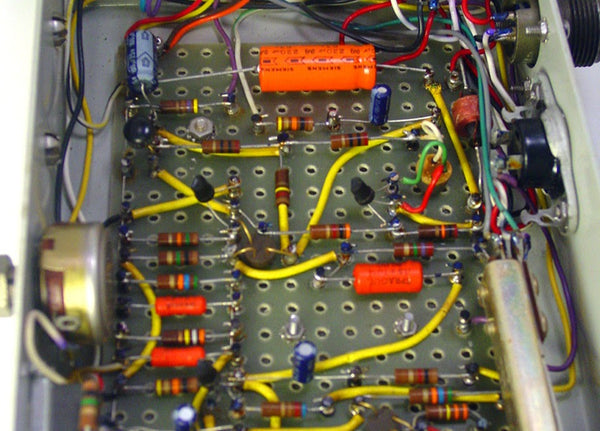
As you can see, assembling electronics used to take a lot of time, skill, and focus! Then PCBs came a long and made everything a easier by building all those wires right into the board itself.
PCBs are rigid boards with pre-wired circuitry, plus some extra perks like soldermask and silk-screening (more on those to come). So these days, instead of painstakingly cutting, bending, and soldering each connection, the assembler just has to solder each component in the right place and the PCB does the rest.
What are PCBs made of?
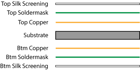
PCBs are made of several layers, like an onion parfait. These layers are: substrate, copper, soldermask, and silk screening. PCBs can have several of each of these layers, but most audio PCBs are "two-layer" boards (top and bottom) with this makeup:
Let's take a look at a very simple PCB, our L2A Passive Re-amplifier, layer-by-layer. To keep things simple, we'll only show the top copper, soldermask, and silk-screen layers.

The core of a PCB is fiberglass. Its job is to be rigid (to hold the parts in place) and non-conductive (so electricity won't pass from one side of the PCB to the other). The holes you see in the substrate are for mounting components to the PCB.

This is where the circuit happens. The copper circles you see are called "pads"; this is where the parts get soldered to the board. The lines are called "traces"; this is what carries the electricity from one part to another. There are only a couple of traces visible here because most of them are on the bottom side of this particular PCB.

Although the pads and traces are made of the same thing, we only want to solder to the pads. So we cover the traces in a layer of polymer called "soldermask" that keeps us from getting solder on the traces.

Finally, we print some silk-screened labeling so that the humans can know where to put the parts.
Can I make my own PCBs?
Yes! Start by learning your way around an ECAD (electrical CAD) program. The most popular free programs are EAGLE, DipTrace, Upverter, and KiCad. My favorite of the bunch is Diptrace, though EAGLE is somewhat of an industry standard among DIYers. Here's what the L2A board looks like in DipTrace:

The best beginners' guide I've found to PCB layout is Dave Jone's PCB Design Tutorial (PDF).
Once you've got a layout, you can either order your PCB from a manufacturer, or etch your own at home.
OSHPark is an amazing, game-changing service that charges only $5 per square inch for three copies of your PCB. Unless you plan to make lots of PCBs at home, you won't beat that price rolling your own, and you certainly won't approach the same quality.
If you just love the idea of making your own PCBs or can't wait for OSHPark to deliver, Make Magazine has a great rundown of all the ways you can roll your own.
Any other questions about PCBs you like me to answer?
Let me know in the comments!
Our 10 Favorite Places to Buy Parts (that aren't Mouser or Digi-Key) June 3, 2016 14:33
A huge part of what we do here at DIYRE is "sourcing"—finding the best vendor for each part in our kits. What that means in practice is countless hours of scouring the internet and navigating clunky, decade-old parametric search forms for deals on parts.
Some people actually enjoy this (those people are broken inside), but for those of you who don't we've compiled this list of our favorite sources.
- Redco Audio: One-stop shop for jacks and cabling. Simply the best prices anywhere for Neutrik jacks.
- OSHPark: Get your own PCBs made for cheap in the US! OSHPark has an awesome online ordering system, charges a very fair price of $5/square inch, and sends you 3 copies of your PCB within 2-3 weeks. We use them monthly for our prototypes.
- Apex Jr.: Specializes in buying vintage overstock. Great for old tubes, transformers, and weird stuff!
- Edcor Electronics: Transformers made-to-order in the USA for incredible prices. We use their PC10:10k in our L2A Re-amplifier.
- McMaster-Carr: The hardware superstore with the coolest website in the world. Get your nuts, screws, standoffs, etc. here in every size and finish imaginable.
- MonoPrice: Known for cheap earbuds and USB cables—but have you seen their audio adapters section? The perfect place to stock up on those magically disappearing TRS adapters.
- Bitches Love My Switches: Cheap guitar pedal parts with an attitude. Great prices on 1/4” jacks, switches, knobs, and cases.
- Tayda Electronics: Tayda was introduced to me as, “the site that brazenly undercuts everyone else.” I’d say that’s about right. Tayda stocks generic versions of the essentials for prices that beggar belief. And here’s a pro tip: always check Tayda’s Facebook page for their monthly 15% discount code before your order.
- All Electronics: You might be aware of the huge distributors like Mouser and Digi-Key. But sometimes their gigantic catalogs are more confusing than convenient. That’s why I like All Electronics as a general parts store—they have almost everything you’d want, but not in every variety, brand, etc.
- AliExpress: Need 1-100 of a unique part of questionable quality and mysterious origin? Look no further than AliExpress. How about 100 mic capsules for $0.07 each? Or 100 Neve-style knobs for $0.50 each?
I hope this list saves you a few hours hunched over a computer (that you could have spent hunched over a soldering iron!) and leads you to some good deals. If you know of any gems we missed, please let us know in the comments.
Designing a Tin Can Piezo Microphone December 1, 2015 18:08
Today's blog post is written by Glen van Alkemade of Zeppelin Design Labs.
Introduction
Most DIY audio enthusiasts are familiar with the standard “tin can mic” (or variations thereof), in which a piezo disc is taped onto the bottom of a tin can and then plugged into a high impedance voltage amplifier, like a guitar amp. These types of microphones are nice because they are so easy to make, but they are quite limited in most other areas, including bandwidth, microphonics, signal-to-noise ratio, impedance matching, and cable driving. These issues usually result in a very noisy and brittle sounding microphone. To overcome these limitations, we at Zeppelin Design Labs developed the “New and Improved Tin Can Microphone” (Figure 1), which is described in detail in this Instructable. Using common household items along with a simple circuit, this mic has a tonality similar to the classic tin can mic (for all you Tom Waits fans), but improves upon nearly every other feature.
This article will explain the essential design considerations we put into our Tin Can Mic. You should be able to adapt and apply these principles to your own unique project.

Figure 1
The Essentials
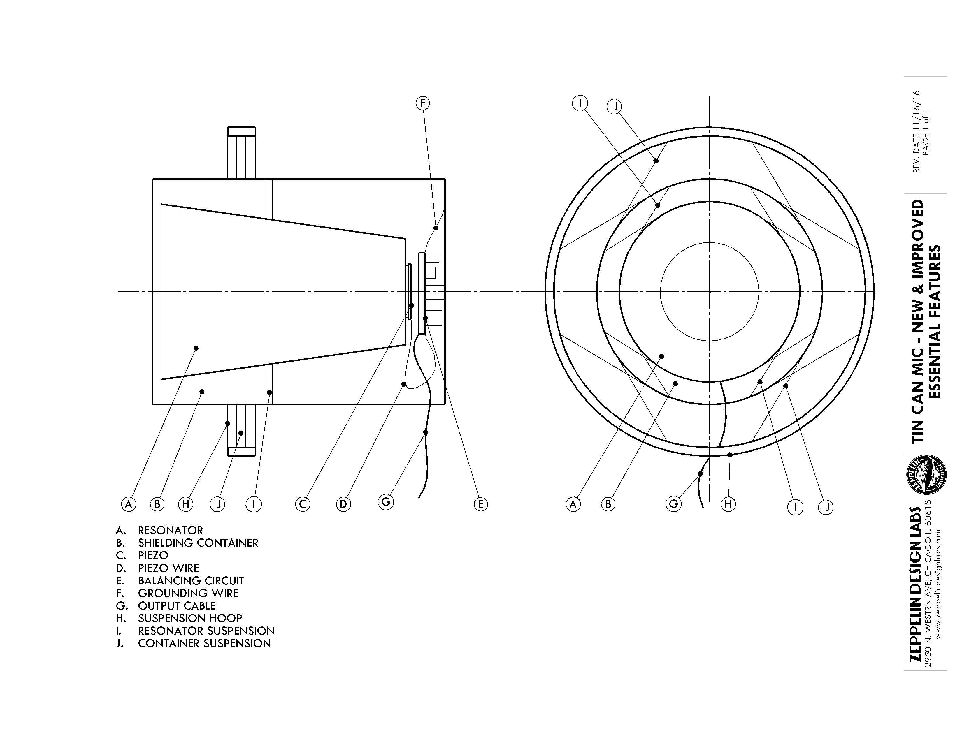
Figure 2 (Click to enlarge)
Figure 2 illustrates the essential components of our Tin Can Mic. These are the parts that we think are key to the performance of the microphone. They include the Resonator (A), the Shielding Container (B), the Balancing Circuit (E) and its Grounding Wire (F), and the Resonator Suspension system (I). Following are some comments on each of these features with suggestions for variations and custom mods.
Balancing Act
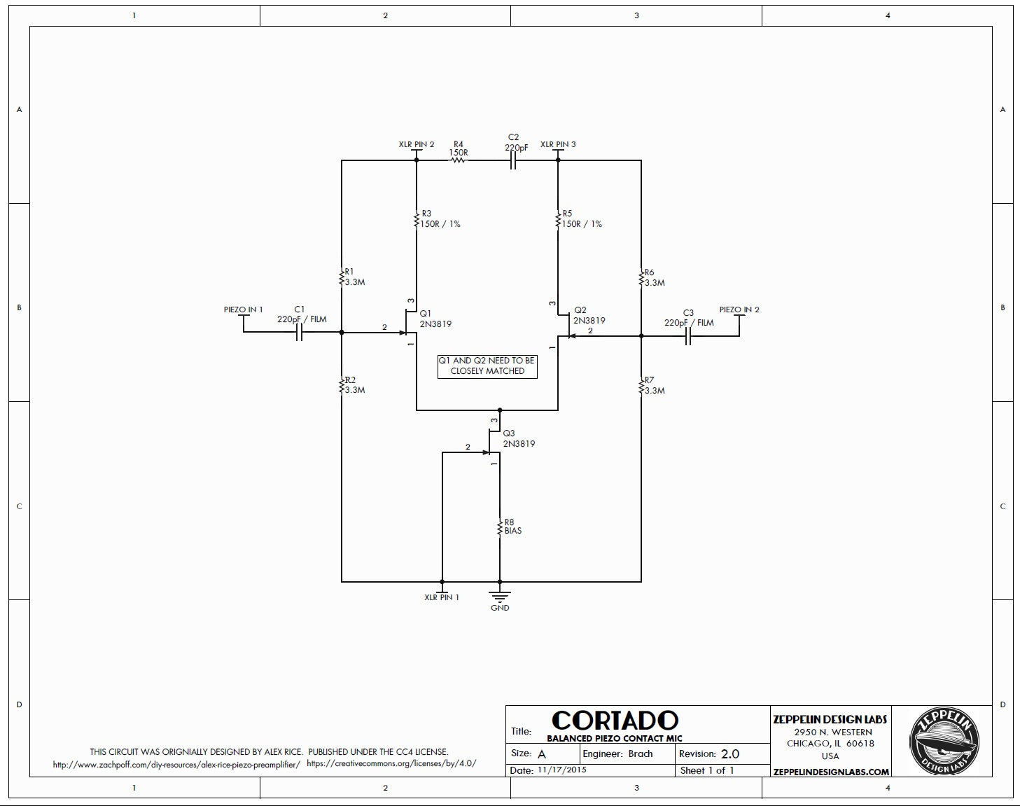
Figure 3 (Click to enlarge)
The heart of the mic is a tiny phantom-powered circuit (originally designed by Alex Rice) which creates a balanced output signal from the piezo disc. A balanced signal is extremely quiet, providing high signal-to-noise ratio. Further, this circuit provides a high input impedance to the piezo disc, and also a low output impedance to match a mixing console input. By properly matching the input and output impedances we achieve a much wider bandwidth than the original tin can mic, and also the circuit can drive the signal along a very long run of mic cable. Figure 3 shows the schematic of our circuit, which we call the Cortado. Our Instructable includes a complete bill of materials from which you can build your own circuit, or you can get a kit from Zeppelin Design Labs.
Speak To Me, or, That Really Resonates With Me
The one piece that most affects the tonality of the microphone is the Resonator, the thing the piezo is stuck to. A piezo disc does not respond to sound in the air; it is only sensitive to vibrations in a surface to which it is stuck, or “coupled”. For the resonator, you want an object that is stiff enough to propagate sound vibrations, but light enough to respond to your voice in the first place. For example, a thin piece of foam padding is very lightweight, and your voice is loud enough to cause it to vibrate. But it is very soft and flexible, and the energy of your voice is quickly absorbed by the foam. A plate of glass will transmit sounds instantly and with great fidelity, but it takes a lot of energy to get a plate of glass to vibrate. You could use a piezo to record the sound of marbles pattering on a glass pane, but even if you shout at that glass, your mic will likely hear nothing.
For these reasons, we settled on a Styrofoam cup for our resonator. There are many other common objects you could use for the resonator: paper cups -- small or large, waxy or plain; plastic cups; plastic food containers of various materials, shapes and sizes; aluminum cans; and of course the original, a steel soup can. Each one will sound significantly different. Even trimming the curled lip off the end of a paper cup will affect the tone. Experiment!
Stick it to me!
For maximum bandwidth, the piezo needs to be tightly coupled to the bottom of the resonator, Figure 2 (C). We think the best thing to use for permanent installation is a good quality double-sided tape (carpet tape), but various glues could work too. Glues will likely filter the sound in different ways. If you want to try the piezo on lots of different resonators, you can just use masking tape or painters tape temporarily.
For the piezo to respond to the vibrations in the Resonator, it is important to use very fine, flexible wire between the piezo and the circuit (D). We use 30 gauge wire in the Cortado. We have found that the wires inside a computer monitor cable make an excellent choice.
EMF Defense Shield
To eliminate noise from the circuit, every element must be carefully shielded, from the piezo all the way to the recorder input. This is why the Resonator, piezo and balancing circuit must all be contained within a conductive Shielding Container, Figure 2 (B). Additionally, the Shielding Container must be grounded to the circuit (F), and you must use a decent-quality shielded mic cable coming from the circuit output (G). You may want to wrap up your circuit board in electrical tape, and secure it to the inside of the Shield Container. In our design, we use a standoff and a couple of tiny screws to mount the circuit board to the bottom of a soup can. Just make sure the circuit can’t short out to the shield, or bump into the resonator.
The shield can take many forms, but must be made of a conductive substance, and must close around the mouth of the resonator close enough to intercept electromagnetic fields that may be approaching. Thus a trash can would not make a good shield, but a length of pipe would be excellent.
I Can’t Stand the Suspense
To eliminate microphonics (the transmission of unwanted signals produced by mechanical vibration), we suspend the Resonator in the Shield with rubber bands. See Figure 2 (I) and our Instructable. The point is to string something elastic back and forth across the shield to form a square into which you can push the resonator. Rubber bands work great; so does sewing elastic, or even lightweight bungie cords. Place the suspension so as to nicely balance the resonator. Be careful to leave clearance for the circuit below the resonator. If the lip of the resonator insists on projecting outside the shield, just trim it off.
We go an extra mile with our Tin Can Mic: we suspend the Shield itself in a Hoop (Figure 2 (H, J)). We use rubber bands for this too, but boy would it look great with little springs! To the hoop we glue an adaptor nut so we can mount it to a mic stand. You will devise any number of clever ways to mount or suspend your mic.
Soup’s On
So those are the basic design elements: a balancing, impedance-matching circuit; stiff, lightweight resonator; well-coupled piezo; careful shielding and grounding; and a springy suspension system. Within these general guidelines, you can make a million different microphones, each with a unique tonality.
21 Ways of Stating Ohm's Law August 11, 2015 16:31
Ohm's law is the key to understanding basic electronics. It describes how the three elements of electricity—current, voltage, and resistance—relate to each other. Ohm's law can be expressed as an equation three ways:
- I (current) = V/R
- V = IR
- R = V/I
Which is crystal clear if you've studied electronics for years. Most of us need to hear it rephrased in plain language dozens of different ways before it clicks.
All of the statements below are simply ways of restating the equations above. Each one is pretty dense and many will be counter-intuitive. Take your time to unpack them, and leave your questions in the comments if anything doesn't make sense.
I hope one of them makes Ohm's Law click for you.
- Voltage is how much current will flow through a conductor of a certain resistance.
- Voltage is the resistance of a conductor given a certain current.
- Resistance is how much current will flow given a certain voltage.
- Resistance is how much voltage will be generated by a certain current.
- Current is how much voltage will be generated by a certain resistance.
- Resistance is the ratio between voltage and current.
- Current is the resistance of a conductor given a certain voltage.
- Resistance is how easily voltage can increase current.
- Voltage makes current flow through a conductor.
- If voltage is fixed, increasing resistance will decrease current.
- If current is fixed, increasing resistance will increase voltage.
- If resistance is fixed, increasing voltage will increase current.
- If resistance is fixed, increasing current will increase voltage.
- Current is proportional to voltage; resistance is the constant of proportionality.
- Without any of the three, there’s no electricity. (Try putting zero in any of the equations.)
- Current moving through a conductor creates voltage.
- You can’t have voltage without current, current without resistance, etc.
- “Danger: High Voltage!” could also be correctly written “Danger: High Current and Resistance!”
- If resistance is very low, you can get a ton of current with a very low voltage. (eg. 1 Volt / 0.001 Ohms = 1,000 Amps).
- If resistance is very high, you get very little current even with very high voltage (eg. 1 Volt / 1M Ohms = 1 micro Amp).
- If you know two, you can always figure out the third.
"Explain Like I'm 5": Opamps July 21, 2015 14:09
What are opamps?
Opamps (or op-amps, or operational amplifiers) are small, inexpensive integrated circuits that can be used to do a ton of different things in audio electronics. They can apply gain or attenuate a signal, create filters, present desired input/output impedances, oscillate at specific frequencies, etc.
They’re usually manufactured on a black, spider-like component with at least five terminals:
- +Power
- -Power
- +Input
- -Input
- Output
What do opamps want?
Instead of talking about how opamps work from an electronics perspective, it’s easier to think about what they want. Opamps want their inputs to be equal all the time. So if the voltage at both inputs is 0, the opamp is happy–it doesn’t need to do anything at all. But the second we change the voltage at one of its inputs, the opamp will jump into action immediately to give the other input that same voltage. Absolute equality–that’s all it wants.
Opamps are so committed to this single desire that they will burn themselves out in a plume of noxious smoke before admitting defeat.
How do they get what they want?
Opamps use their outputs to make their inputs equal. But they can’t do this on their own–they need us to provide a feedback path. Let’s say we kindly oblige and solder a wire between the output and - input pins. (This is called negative feedback.) Now whatever voltage the opamp sends to it’s output gets immediately sent to the - input as well. In other words, if the + input is fed a certain voltage, the opamp can immediately make the - input the same by adjusting its output voltage. In other words, it can get what it wants!

Negative feedback
Now let’s do that with numbers so you can see what it looks like. Say we connect a microphone with a 1V output to the opamp’s + input. The opamp wants to make - input 1V as well so it sets its output to 1V. And since we’ve attached a negative feedback wire, that 1V is immediately sent to the - input. Now both inputs are sitting at 1V and the opamp is happy.
How we make them do what we want?
That’s all well and good, but if we stopped there the opamp would only be good for passing unity gain. The real fun comes in replacing that feedback wire with some more interesting components. Let’s say we replace it with two resistors configured as a voltage divider.

A voltage divider in the negative feedback loop
These resistors will take the voltage from the output and cut it in half before it reaches the - input. Let’s go back to our example from the previous section. If the output were still set to 1V, the - input would be at only 0.5V. And that’s not what the opamp wants! So now it adjusts its output to 2V to get 1V back to the - input. The opamp is happy again and our microphone signal is 2x (6dB) louder at the output of the opamp.
And gain is just the beginning. We can put all sorts of stuff in the feedback loop: capacitors and inductors for filters, diodes for clipping, transistors for variable gain–you can even put other opamps in there! The point is that the opamp just wants one simple thing–to make the inputs equal–and we can make it do all sorts of stuff just by making it work harder to make that happen.
How do opamps work?
I honestly have no idea. I’ve never designed one or even bothered to look at one’s schematic diagram. But that’s the beauty of integrated circuits: you can treat them like a black box. If you understand their specs and theory of operation, you can use them without knowing what’s going on inside.
Why are there so many kinds of opamps?
All of design is basically managing tradeoffs: more gain vs. more noise, greater bandwidth vs. less stability, greater precision vs. higher cost, etc. There are hundreds of different opamps and they all do the same thing but make different tradeoffs. So one opamp may be ultra-low noise, but have stability issues at high gains. Another may be very low cost but have lots of noise. And so on.
What are discrete opamps?
99% of opamps you’ll come across are monolithic, as opposed to discrete. They look like the spider thing below and are manufactured in massive quantities on silicon chips.
A standard monolithic opamp IC
But some folks in the audio community are not content to pick from the variety of monolithic opamps available. They prefer to roll their own by placing individual components on a printed circuit board. They are big and expensive and usually sport “worse” specs than even low-end monolithics, but they have certain benefits like being proprietary and high-margin entirely customizable to suit the designer’s ears.

Image courtesty of 6SN7, licensed under a Creative Commons License
Do different opamps sound different?
There's much debate over how significant the audible differences are between different opamps. Some people (often musicians) claim to hear a "night and day" difference when they swap the opamps in an old piece of gear. Some people (often engineers) claim there's no difference at all.
I've spent a good bit of time listening to different opamps in a controlled environment and my take is that audible differences between opamps are vanishingly small when they're operated in their linear range. When you start to ask them to do stuff beyond what on their spec sheets, all bets are off.
So, swapping an opamp that's just a buffer between two stages in a compressor? Probably not gonna hear much of a difference. Swapping opamps in a circuit with a hot input signal and excessive amounts of gain? You will hear major differences, akin to using two different mic preamps to apply a lot of gain.
Did I miss anything?
I hope that helped clarify things a bit! Is anything unclear? Let me know in the comments if you have any other questions about opamps I can answer.
Exactly How the LINE2AMP Reamping Box Works (and Why) July 19, 2012 13:30 19 Comments
Why do we need a reamping box? People have been plugging line-level signals into guitar amps since long before the first reamping box hit the market, often with good results. This is true; in many cases, simply plugging the output of your interface into an amp and crossing your fingers is good enough. However, what we want is to be able to plug any line-level device into any instrument-level input and have it sound right every time. In order to do this, we need a device that addresses the following issues:
- matching volume levels;
- interfacing balanced and unbalanced gear;
- emulating line and instrument impedances;
- ground-related noise.
As so rarely happens in audio and electronics, there is a cheap, simple, and ideal solution to all of these problems: an audio transformer. Let’s look at the ways a humble audio matching transformer can make reamping a consistent and transparent process.
Attenuating the Signal
The nominal level for a professional line-level signals is +4dBu, or approximately 1.2 Volts rms. Guitar signals, on the other hand, vary between a few tens of millivolts rms to 1 Vrms or slightly more depending on the pickup. So, in order to to mimic the output level of an average guitar, we need to attenuate our line-level signal somewhat before sending it to an amp. The clear choice for attenuating voltage (“volume” in audio) in terms of cost and complexity is a couple of resistors set up as a voltage divider. However, since we’re already using a transformer to address the other two problems of reamping, we might as well use it to reduce the voltage as well. Modified and reused under the GNU Free Documentation License
To understand how we can use a transformer to attenuate the signal, let’s look at how transformers work. Transformers operate according to a funny feature of our universe called “electromagnetism” by which a changing electrical field induces a changing magnetic field and vice-versa. A basic transformer such as the one we’re using consists of two coils of conductive wire wrapped around a magnetically permeable core, usually iron. The alternating current running through the “primary” (input) coil creates a magnetic field which induces a corresponding voltage in the “secondary” (output) coil. From our point of view, two important things happen to between the input and output of a transformer. 1) The grounds are isolated (which will be important for solving another reamping problem), and 2) the voltage, current, and impedance are transformed in proportion to the ratio between the number of turns of wire in the two coils (the “turns ratio”). Since the issue at hand is volume, let’s discuss voltage for the moment and leave current and impedance for later.  Edcor PC10k/600 transformer
A transformer reduces or increases the voltage of a signal in direct proportion to the turns ratio. If the turns ratio is 2:1, the voltage induced in the secondary will be half of that in the primary. The Edcor PC10k/600 transformer included in the LINE2AMP kit has a turns ratio of 4.1:1, so the output signal is 4.1 times smaller than the input signal. In audio terms, this equates to 12dB of volume attenuation, just enough to get us to an average guitar output level.
Achieving the Correct Impedances
Put simply, “impedance” is the degree to which a circuit opposes the flow of AC current. Impedance is similar to the more basic concept of resistance, except that it is frequency dependent. That is, a circuit may present more opposition to high-frequency than low-frequency signals and vice versa. A great way to de-mystify impedance is to think of it in a realm we're all familiar with: acoustics. Every physical medium presents a certain amount impedance to the propagation of sound. This impedance is not uniform at all frequencies. This is why, for example, we hear the bass drums of a marching band first and higher frequencies connote "presence" to our ears.
There are two impedance values involved when connecting one piece of audio gear to another: that of the output device, called "source" or "output" impedance, and that of the input device, called "load" or "input." These two values tell us (at least) two important things:
- how much of the output signal (voltage) will be transferred to the input device;
- how much power is required for the output device to drive the input device.
Generally speaking, we get optimum results in both of these areas when the output Z is at least 8-10 times lower than the input Z; this is called "bridging" the output impedance. There is a common misconception that the input and output impedances should be matched--forget it, this is not true for audio! So what are the "correct" impedances in a reamping situation? The modern standard for line-level input Z is around 10kΩ, while guitar output Zs vary from below 100Ω for active pickups to 50kΩ+ for passive. In the same way that our transformer induces a different voltage across the secondaries than the primaries, it also transforms impedances. But whereas voltage is transformed in direct proportion to the turns ratio, impedance is transformed in proportion to the square of the turns ratio. Thus, the impedance ratio for our 4.1:1 transformer is 16.81:1, or approximately 10k:600.

We achieve our 10kΩ+ line-level input Z by placing a resistor across the transformer secondaries. The impedance reflected in the primaries is then 16.81 times the value of this resistor (for the LINE2AMP kit I have chosen a 1k resistor). At this point, with only the transformer and 1k resistor, our output Z is equal to the line-level output Z divided by 16.81, i.e., arbitrarily low. We can raise this value to within the range of a typical guitar output Z by adding a resistor in series with the output signal. I chose 15kΩ for this job but any value between 0 (no resistor) and 50k will emulate a different type of pickup.
Balanced to Unbalanced and Ground Noise
Reamping involves interfacing balanced (actually “differential” is correct, but I’ll defer to the parlance of our times) and unbalanced gear. A balanced connection has three parts: signal “hot” (non-inverted, +, tip, XLR pin 2), signal “cold” (inverted, -, ring, XLR pin 3), and ground (shield, chassis, sleeve, XLR pin 1). Balanced gear takes for its signal the difference between the hot and cold signals and ignores anything common to both (including noise). The chassis pin exists to provide unwanted noise a quick path to ground; it is not part of the audio signal.
Modified and reused under the Creative Commons Attribution-Share Alike 3.0 license.Original rendering by Søren Peo Pedersen
An unbalanced signal on the other hand consists of simply signal (tip) and common (“ground,” 0 V, sleeve). In an unbalanced system, the common is the reference for the signal voltage, so any noise injected into the common will in turn affect the signal. In the case of reamping, we are attempting to connect a balanced output from our mixer/interface/whathaveyou to an unbalanced, instrument input. What happens when we do this without properly "unbalancing" the output signal? By connecting the sleeve pins of both devices together we are connecting the the noise return path of the balanced output to the audio common of the unbalanced input. Noise, meet audio. Transformers solve this problem by providing what's called galvanic isolation between the input and output stages. Recall that transformers transfer voltage from one winding to the next through electromagnetic induction, without providing a path for current to flow. Thus, they allow the balanced output stage to "communicate" the signal to the unbalanced input stage without connecting their grounds/commons. It is therefore impossible to a ground loop to exist between the two devices. That's it. An elegant solution to a simple problem. Please feel free to continue this discussion below with your questions, comments or corrections.
Everything You Always Wanted to Know About Audio Electronics (But Were Afraid to Ask) May 30, 2012 12:45 60 Comments

Thanks for all the awesome questions! Stay tuned for the podcast.
One of the biggest obstacles for entry into the DIY community is that most of us arrive here from a music, not electronics background. We've all been there: you're planning your next DIY project and the documentation casually tells you to "bias the transistor." In that moment, very few of us want to be the one to ask, "umm.... what's biasing?" Well, now is your chance to ask all of those audio electronics questions you never found the right moment to ask! On Saturday, 6/9/2012 I'll be recording a podcast with a real live EE who has volunteered to answer your questions. Please post your questions in the comments section by Friday, 6/8 and we'll try to answer as many of them as we can. No question is too dumb or too complex to ask.About the Expert
Duncan Gray is an EE with over 30 years experience in the field, including a stint as a Senior Hardware Design Engineer for Digidesign. His areas of expertise include both analog and digital hardware design, audio transformers, power systems, and scientific programming. Many thanks in advance to Duncan for volunteering his time and expertise!LINE2AMP Design Journey February 15, 2012 20:14 1 Comment
This all started when my grandfather decided to dissolve his woodworking shop and give me his gorgeous old Sears drill press. I couldn't let a tool like that sit idle in my basement, so I thought, hey why not make a DIY kit? That was last August (2011), and while the The LINE2AMP reamping box is about as simple a piece of gear can get, it's been a rather long and circuitous journey to bring it to fruition. Doubtless, someone more experienced could have whipped the LINE2AMP up in a weekend, but I've learned a ton about electronics, product design, and DIY in the past few months. I'll be using this page to share what I've learned with you, as well as to let you in on the design process of the LINE2AMP as it progress.
August 2011: Researching Reamping
My original goals for the LINE2AMP were that it should:- Perform as well as any commercially available unit
- Cost less than $50 to build
- Be simple enough for newbies to build successfully.
I starting looking around at other reamping designs available on the internet and found three popular schematics: Jensen, Recording Magazine (Scott Dorsey), and NYDave. Looking at schematics the schematics, I realized that all of them shared the same essential topology:

I ordered a couple of transformers from Edcor USA to start experimenting with circuits.
September 2011: Prototyping
Four weeks later transformers arrived and I started soldering. 30 minutes later I had a working reamping box. Huzzah! Goal #3 was in the bag. My first prototype hewed almost exactly to NYDave's design: I used the Edcor PC10k/150 transformer with a volume pot and 200 Ohm terminating resistor. The only variation was that I used a 1M Ohm variable resistor to test different output impedances. Testing the prototype with a variety of amps, pedals, and DIs revealed a few things:- The unit was dead quiet and imparted practically nothing on the tone. At first, I had been skeptical about how the unshielded Edcor would perform, as both the Jensen schematic and the Reamp use shielded transformers. While a shielded trafo would certainly be better on paper, in practice the Edcor added no noticeable noise, even when run via DI into a clean preamp.
- The impedance resistor had no noticeable effect on the sound until it was cranked beyond about 200k Ohms, after which the signal started to lose some high frequencies and become distorted in the bass.
- In almost all cases, there was less noise when the connection from ground pin of the input jack to the case was disconnected. Only with some pedals did it sound better connected.
Overall, I was really happy with how the circuit worked. I didn't have a commercial reamping box on hand to shoot it out against, but it did everything a reamping box should and without any noise or sonic artifacts of its own. In fact, I was pretty blown away by the transparency of the Edcor transformer. In a blind test between A) a signal sent first to the reamping box, then the DI input of my Hamptone preamps and B) a signal sent right from my interface to the line input of the Hamptones, I couldn't make any conclusive distinction between the reamped and non-reamped signal.
Paring Down to Essentials
After playing around with my prototype, I realized that the LINE2AMP could be made even simpler than any of the other reamping designs and do the job just as well. The first thing to go was the impedance knob. From one perspective, it makes sense to have a range of output impedance available to emulate the source impedances of different guitars (typically between 10k-50k Ohms) and pedals (as little as 200 Ohms with a buffered output). However, in testing there was no audible change in tone until about 200k Ohms. From a technical perspective this makes sense, as any source impedance below 100k or so would be easily bridged by most guitar amp and pedal inputs. Goodbye to that pot! Next to go was the volume knob. In theory it's nice to have a tactile way to control the level, but in practice I found myself almost always doing it from the DAW. I also rarely found myself wanting less signal, and without adding active circuitry the volume control can only attenuate, not boost. What's left is the bare essentials of a reamping device: a transformer for impedance/voltage conversion and ground isolation, and a resistor to set the input/output impedances. That's it!Work in Progress: The Ultimate Audio Transformer List December 9, 2011 17:37 12 Comments
How awesome would it be to have a list of every transformer you'd ever want to use in a DIY project? Let's do it! Please leave your contributions in the comments section. Thank you to Justin Boland for getting us started.| Manufacturer | Part # | Type | Turns Ratio | Impedance Ratio | Used By |
|---|---|---|---|---|---|
| Carnhill | VTB9045 | Mic In | Neve | ||
| Marinair | 10468 | Mic In | Neve | ||
| Ed Anderson | EA10468 | Mic In | Neve | ||
| Sowter | 9145, 9165 | Mic In | Neve | ||
| Carnhill | CA-18-VTB9071 | Line In | Neve | ||
| Marinair | LO-1166 | Line Out | Neve | ||
| Marinair | LO-2567 | Line Out | Neve | ||
| Carnhill | VTB1148, VTB1847, VTB9049 | Line Out | Neve, Trident | ||
| Ed Anderson | EA1166 | Line Out | Neve | ||
| Sowter | 8751, 9160 | Line Out | Neve | ||
| Sowter | 9780 | Line Out | Neve | ||
| Cinemag | CMOQ-2S | Line Out | Neve | ||
| Crimson Audio | CT-2385 | Line Out | Neve | ||
| JLM Audio | JLM111DC | Line Out | Neve, Trident | ||
| API | 2622 | Mic In | 1+1:7 | 150/600:10k | API |
| Ed Anderson | EA2622 | Mic In | 1+1:7 | 150/600:10k | API |
| Cinemag | CMMI-8PCA | Mic In | 1:8 | 150:10K | API |
| Sowter | 9820 | Mic In | 1:4.37 | 150/600:11.5k | API |
| API | 2503 | Line Out | 1:1, 1:2, 1:3 | 75:75, 75:300, 75:600 | API |
| API | 2623 | Line Out | 1:1, 1:2 | 75:75, 75:300 | API |
| Ed Anderson | EA2623-1, EA2623-4 | Line Out | 1:1, 1:2 | 75:75, 75:300 | API |
| Ed Anderson | EA2503 | Line Out | 1:1, 1:2, 1:3 | 75:75, 75:300, 75:600 | API |
| Sowter | 9825 | Line Out | 1+1+1+1 | 75:300+75 | API |
| Cinemag | CMOQ-2L | Line Out | 1:1 | API | |
| API | 2164 | Line In | 10k:600 | API | |
| Jensen | JT-16-B | Mic In | 1:2 | 150:600 | John Hardy |
| Jensen | JT-11-BMQ | Line Out | 1:1 | 600:600 | John Hardy |
| Jensen | JE-6110K-APC | Mic In | 600:150/10k | Auditronics | |
| Jensen | JE-123-S | Line Out | 1:1 | 600:600 | Auditronics |
| Sphere | 7341 | Mic In | Sphere | ||
| ZUTT | 012A, 782A | Mic In | 1:5.63 | 1.2k:38k | Trident A, B, and Fleximix* |
| ZUTT | 783A | Line In | 1:1 | 15k:15k | Trident A, B, and Fleximix* |
| Sowter | 7456 | Mic In | 1:5.9 | 600/30K | Trident |
| Jensen | JT-13K7-A | Mic In | 1:5 | 150:3.8k | Trident |
| Sowter | 3553, 2318, 3777 | Mic In | Calrec* | ||
| Sowter | 3955 | Line Out | 1:1.06 | 600:600 | Calrec* |
| Triad | A-67J | Mic/Line In | Spectra Sonics* | ||
| Triad | HS56 | Mic/Line In | 1:1 | 600:600 | Pultec, Spectra Sonics |
| Sowter | 3603 | Mic/Line In | 1:1 | 600:600 | Pultec, Spectra Sonics |
| UTC | LS30 | Mic/Line In | Spectra Sonics | ||
| Triad | HS66 | Line Out | Spectra Sonics* | ||
| St. Ives | VT22670 | Mic In | Neve* | ||
| St. Ives | VT22671 | Mic In | Neve* | ||
| Marinair | T1422, T1442, T1452 | Line In | Neve* | ||
| UA | 5002 | Line Out | UREI 1176 Rev A-E* | ||
| Bournes | B11148 | Line Out | UREI 1176 Rev F-H | ||
| UTC | 012 | Line In | UREI 1176 | ||
| Jensen | JT16A | Mic In | Sunset Sound Console | ||
| Edcor | PC10k/150 | Line Matching | 8.2:1 | 10k:150 | LINE2AMP Reamping Box |
| Cinemag | CM-9888 | Mic Out | 1:28 | Ribbon mic | |
| Lundahl | LL2912 | Mic Out | 1:37 | Ribbon mic | |
| Sowter | 8074 | Mic Out | 1:40 | Ribbon mic | |
| Edcor | RMX1 | Mic Out | 1:37 | Ribbon mic | |
| AMI/TAB Funkenwerk | T42 | Mic Out | 1:42 | Ribbon mic | |
| AMI/TAB Funkenwerk | T58 | Mic Out | Shure SM57/SM58 Mod | ||
| Samar Audio | RT36 | Mic Out | 1:40 | Ribbon Mic | |
| Monacor | LTR-110 | Line Matching | 1:1, 2:1 | ||
| Monacor | DIB-110 | Direct Box | 10:1 | ||
| Lundahl | LL1538 | Mic In | 1:5 | Focusrite, Trident, GP Electronics | |
| Lundahl | LL1517 | Line Out | 1 + 1:1 + 1 | Calrec | |
| Altran | C-3837-1 | Line In | 1.58:1 | 500:200Ω | DIY 1176 |
Simple Guide to DIY Electronics #1: Passive Components August 16, 2011 16:31
Electronic components are called 'passive' when they don't produce gain or require a power supply to function. While there are numerous components that meet this definition, when we refer to 'passive components' we usually mean the following three types: resistors, diodes, and capacitors.
Resistors
Resistors are those little, candy-looking tubes that populate almost every audio project in great numbers. Their job is to present a certain amount of opposition, or resistance, to the electrical current flowing through them. There are three specifications you'll use to identify the correct resistor for a certain job:- Resistance: The amount of resistance, measured in in Ohms (Ω). This is usually indicated on the surface of the resistor with color-coded stripes.
- Tolerance: The degree of precision to which the resistor was manufactured. For example, a 1k resistor manufactured to ±1% tolerance may have an actual value between 990 and 1.1k ohms. This is also typically indicated with a color-coded stripe.
- Power: The maximum power (heat) a resistor can dissipate without being damaged. This is not specified on the body of most resistors, but can often be guessed from the resistor's physical size with a little experience. Most resistors in audio circuits dissipate less than 1/2 Watt of power.
- Resistive Material: Resistors are made from a wide range of materials, but the most common in audio circuits are:
-
 Metal Film: By far the most common in modern equipment. They are nearly transparent in audio circuits and can be made cheaply to very strict tolerances.
 -
 Carbon Composition: Long since surpassed by film resistors in terms of noise and precision, carbon comps are nonetheless still used, especially in circuits that attempt to clone a vintage unit. Many vintage guitar pedal enthusiasts, for example, use exclusively carbon comps.
 -
 Carbon Film: Precise and low-noise enough for most audio applications. Often used when a certain value or power rating is not available in metal film.
Capacitors
Capacitors ("caps" for short) are the second most common component in audio projects. They are designed to store and discharge a certain amount of energy and play a wide range of roles in circuits, from smoothing power to filtering frequencies from an audio signal. There are three important specs that define a capacitor:- Capactiance: The amount of capacitance, measured in farads. Common subdivisions of the farad are micro-farads (uF) nano-farads (nF) and pico-farads (pF).
- Voltage: The maximum operating voltage.
- Polarity: Some capacitors are polarized and must be installed a certain way in order to remain in their "unexploded" state :O If a capacitor is polarized, its polarity will be marked on the body of the capacitor and accordingly on the schematic or PCB in which it is used.
-
 Ceramic: Small, non-polarized, usually used as bypass caps.
 -
 Electrolytic: Capable of high capacitance per volume, usually polarized.
 -
 Silver Mica: Linear and stable, but relatively large and expensive.
 -
 Polyester: Low tolerance and low voltage, often seen in audio circuits.
 -
 Polystyrene: High stability, low distortion.
Diodes
Diodes are components that allow current to flow through them in only one direction. A diode's two leads, the anode and the cathode, will usually be labeled and must be installed correctly in order for the diode to work properly. Common types of diodes found in audio projects are:-
 Light Emitting Diode: Emits light when current passes through it. The anode is indicated by having a longer lead than the cathode.
 -
 Schottky Diode: Designed to cause as little voltage drop as possible. The cathode is usually marked with a silver stripe on the diode's body.
 -
Zener Diode: Operates like a standard diode until a certain voltage is reached, when it allows current to flow both ways. The cathode is usually marked with a stripe.
- The noob's guide to DIY jargon.
- It's hard to beat Rod Elliott's beginners' guide to electronics, also written from an analog audio perspective.
Getting Started: 21 newbie-friendly DIY projects July 12, 2011 18:04 3 Comments
When you're first getting turned on to the world of DIY, it's easy to be tempted by projects that are beyond your abilities. Be Realistic. High voltages and hot solder are no joke and the last thing you want to do with your first project is end up with an expensive heap of broken equipment. To choose a first project that will build your skills and confidence, look for something that meets these guidelines:- Low voltages (no tubes, sorry)
- Prefabricated case and front panel
- Power supply included (pre-assembled is a plus)
- Through-hole components only (no SMD)
- Complete kit (no components to source)

Starting Small
I created the LINE2AMP reamping box and Endless Summer analog summing box kits with absolute beginners in mind. Both are completely passive and have been successfully built by numerous first-timers. My first DIY project was the 250+ distortion pedal from Build Your Own Clone. The fruits of that project were an awesome sounding pedal and the confidence to take on a mic preamp for my next project. There are literally hundreds of pedal projects out there which I'm still working on cataloging, but I know first-hand that BYOC's inlcude excellent, step-by-step instructions. Difficulty: 1-4
Fill Out Your 500-Series Rack
One easy way to get around the dirty business of choosing a power supply, wiring connections, and cutting holes in a case is to build modules for the API 500-series "Lunchbox" format. The 500-series modules that I recommend for beginners are:-
ClassicAPI VP25/26 or 312 Preamps
ClassicAPI's kits clone the simple API circuit with a roomy layout. This, along with good documentation and the option for pre-assembled opamps, make these the surest bet for your first 500-series project.
Difficulty: 4 -
Sound Skulptor MP573 Preamp
If you want to tackle a Neve preamp off the bat, be prepared to face a more complex circuit with little room for sloppy soldering. However, if you've got experience with a soldering iron, this full kit provides perhaps the easiest way to build a Neve-style preamp.
Difficulty: 6
Full Kits
These kits contain everything you need to complete the project, except, of course, the proper tools. Microphones
- Austin Ribbon Microphone Difficulty: 2
-
PAiA Project R
Difficulty: 2
 SCA Preamps
- A12 (API-style) Difficulty: 4
- C84 ("Neutral"/Millennia-style) Difficulty: 6
- N72 (Neve-style) Difficulty: 6
- J99 (Twin Servo) Difficulty: 6
- T15 (THAT1512-based) Difficulty: 3
 JLM Audio Preamps
- Baby Animal Difficulty: 5
- 1290 Micro (Neve-style) Difficulty: 5
- Mono Portable Preamp Difficulty: 2
 Sound Skulptor Preamps
- MP12 (API-style) Difficulty: 4
- MP32 ("Neutral"/Discrete Opamp) Difficulty: 4
- MP66 (Tube) Difficulty: Not Recommended for Beginners (high voltage)
- MP73 (Neve-style) Difficulty: 6
 FiveFish Preamps
- SC-1 ("Neutral"/THAT1512-based) Difficulty: 5
- X-12 Difficulty: 5
 Hamptone Preamps
- HJFP2 (JFET) Difficulty: 5
- HVTP2 (Tube) Difficulty: Not recommended for beginners (high voltage)
Thanks for reading--I wish you the best of luck with your DIY undertakings. If you have any questions before starting your first project, feel free to ask them on the Q&A board.
5 Ways to DIY With Discrete Opamps June 17, 2011 11:09 5 Comments

This week, I was lucky enough to receive a pair of GKL255 discrete opamps in the mail from Bearcat Audio, the newest vendor on the DIY Recording Market. (Thanks guys!) Even as I opened the parcel from Montreal, my mind was already thumbing through the projects in my DIY to do/wish list for a special place to socket these new DOAs. But first, a little overview of discrete opamps for the beginner:
An operational amplifier (opamp) is a single-ended differential amplifier. This means it takes two inputs, inverted (-) and non-inverted (+), and produces a single output which is many orders of magnitude larger than the difference between the inputs. Usually opamps are manufactured as monolithic integrated circuits (ICs); however, a few intrepid designers have created their own using discrete transistors, resistors, capicitors, etc. There are three classic DOAs that most DIYers have tried to clone, imitate, or "improve": the Melcor 1731, API 2520, and Jensen 990. Each classic opamp has it's own sound which, without getting into too much audiophoolishness, can summed up thusly:- Melcor 1731 (1960's): Smooth highs and lows, beefy harmonics
- API 2520 (1970's-): Aggressive mids, solid lows, classic 70's coloration
- Jensen 990 (1980-): Low-distortion, fast transient response, wide open sound
1. Build an API or Jensen style mic preamp
The 2520 discrete opamp is at the heart of the "API Sound." And these days, there are a cornucopia of projects for the API-style preamp builder, including:
- Access 312 and Bicycle 312 are PCBs for 312-type preamps
- FiveFish X12, Seventh Circle A12, and Sound Skulptor MP12 are complete kits for building preamps in rack-mount enclosures
- Bearcat 412 a complete kit for building four 312-inspired pre's in a 1RU chassis
- ClassicAPI's VP25, VP26, 312, and 312DI are 500-series replicas of API circuits
The 990 DOA was used in several very successful preamps, including Jensen's twin servo design, which utilized two Jensen opamps and transformers. Seventh Circle Audio's J99 kit is a version of the twin servo with SCA's own 990-type opamp and Lundahl and Cinemag transformers. It's also possible to create a Jensesque preamp with JLM Audio's Baby Animal Dual kits, using any 990-type DOA and Jensen transformers.
2. Concoct your own preamp design
One of the distinct pleasures of building with discrete opamps is that they have a common footprint and can often simply be swapped. This makes the basic transformer/single opamp preamp design a great platform for experimenting with new component combinations.
- JLM's Baby Animal kits provide such a platform with a pre-fab power supply and chassis so you can focus on transformer and opamp choices.
- The Bicycle 312 Hybrid PCB is also a great place to start if you want to build your units from the ground up.
3. Build a ClassicAPI "Missing Link" Console Channel
One theory about the lack of "mojo" or "warmth" in modern recordings is that we're simply not running audio through as many transformers and gain stages as they did in the days of the large-format console. Preamps, in other words, were only part of what made those consoles sound so good. ClassicAPI provides some consolation for the console-less in the form of the VC528 ST+ console channel for the 500-series/51x Alliance. The VC528 "completes" a preamp with a fader, filters, and an output amp, running the signal through two transformers and discrete opamps of your choice along the way.
5. Make a unique hybrid 1176 compressor
Igor's 1176-style compressor for the 51x Alliance/500-series, the F76 FET, provides the option to replace the original amplifier stages with DOAs. Why not be the only engineer in town--heck in the county, heck in the tri-county area--with an "API 1176"!?
6. Upgrade the DIP8 opamps in your mixer, compressor, equalizer, converters, etc.
Until yesterday, June 16th, 2011, the sacrifice you made for using high-quality discrete opamps was not being able to use them in modern DIP8 format gear. AC Sound has begun briding this gap with a series of discrete opamps in the DIP8 format. The opamps will come in "tall" and "wide" formats and M, A, and J models (can you guess what the letters stand for?) AC Sound listed the first set of model A's on the market yesterday and plans take pre-orders the "J" and "M" models soon. Your cheap monolithic opamps had better watch their backs!
DIY Meets the API 500-series May 29, 2011 22:36
One of the most exciting trends in gear over the last few years has been the rising popularity of API's 500-series "Lunchbox" format. 500-series racks such as the Lunchbox provide an easy way to rack and power 6-11 preamps, compressors, equalizers, etc. in a single 3RU case. These racks are a boon to DIYers who want to build their own modules but don't have the skills or tools to drill and engrave their own cases.

Of course, the DIY community has found ways to have their own fun with the format. The first DIY module to the scene was Eisen Audio's DIY500 which provides a PCB and all of the hardware needed to build a transformer-balanced, opamp-based (API, Twin Servo, et al) mic preamp. Great for those who like to tinker, or if you've got some rare iron or a vintage opamp languishing in your collection. Next to come were ClassicAPI's API-style preamps for the 500-series. Created by a 70's API console owner/repairman/admirer, the VP25/VP26 and the VP312 are almost exact replicas of the original preamp circuits. ClassicAPI has also worked with Ed Anderson and Barnett Industries to clone vintage API transformers and opamps. This all makes the VPxx preamps perhaps closest thing out there to the original units--closer, in fact, than those offered by API today.

After modules had been cropping up for a couple of years, some DIYers started daydreaming about a uniquely DIY modular format. The result is 51x, a format based on the 500-series but with both +/-16v and +/-24v power rails. Last year a group of builders created the 51x Alliance 511 Rack, a DIY, 3RU, 11-space rack with an optional power supply kit. Awesome! Now we have a modular rack with a truly bulletproof power supply and enough voltage to power a real Neveish preamp, a John Hardy DOA, etc. Since the introduction of the 511 rack, the GroupDIY forum has exploded with new modules taking advantage of the higher power rails, such as Don Classics Neve clone, Igor's SSL buss compressor, and Classic API's VP312DI. And there's more to come: [silent:arts] has posted pictures of an optical compressor based on the D-AOC and Igor has announced an 1176-style FET compressor. Jeff Steiger of ClassicAPI even has plans for a 500-series/51x console (!!!) with the prototype for a "second console stage" fader and HPF/LPF module already posted. It's a great time to be alive and to DIY!
The Complete Guide to UREI/Universal Audio 1176 Revisions April 18, 2011 08:56 3 Comments
Times are good for building a DIY 1176. Where 1176's used to dangle from big-name engineers' racks like so many fruits from Tantalus' tree, they're now well within reach of anyone with a soldering iron and a modest budget. And where there was once but one DIY option (Gyraf's G1176), there are now a myriad to choose from. But why, indeed, so many projects when there is only one 1176? Revisions. According to Universal Audio's website, the 1176 underwent at least 13 revisions from 1967 to 1973. Most of these consisted of either cosmetic makeovers, such as rev H, or minor tweaks that didn't reach the audio path, such as revs D and E. Others, however, were overhauls that significantly affected the compressors' sonic character. With "Mnats" (a veritable Bill Putnam of the DIY world) now offering PCBs for revs A, D, and F/G, "which one should I build?" is becoming a common question. So without further ado, let's look at the revisions and what they can do for your sound...1176 Revison History
Revisions A/AB June 20, 1967: Wild transients tremble in fear of the enigmatic "Blue-Striped Terror."

Bill Putnam created the first 1176 compressor in 1967. Although it was the basis for all 1176 revisions, the rev A has numerous peculiarities that set it apart from the others. It is the only revision to use FETs rather than bipolar transistors in the preamp and line amps. It is also cosmetically unique, sporting a distinctive blue stripe through the meter. Finally, the rev A does not have the low-noise circuitry of later revisions, which means it imparts more harmonic distortion at the expense of a higher noise floor. The Universal Audio website tells us that there were only 25 of this revision made (serial no. #101-125), which makes them about as rare as a piece of gear can be.
Mnats' Rev A PCB is actually based on what UA calls "rev AB," which changed some resistor values and added a bypass cap for the resistor feeding the gain-reduction FET. So, for all intents and purposes it is a rev A 1176, but with a more stable and controllable limiter.
Revisions C/D/E 1970: A clean up, a suffix, and a dark new look.

Most 1176 fetishists reading this have already noticed two conspicuous differences between the rev A and the compressor most of us know today: the black front panel and the "LN" signification. These were both introduced with rev C and codified with the rev D. "LN" stands for "Low Noise," and all of the circuit changes in rev C were intended to reduce noise and distortion. These include reducing the voltage going to the gain-reduction FET to make its operation more linear, and incorporating a Q-bias pot to minimize distortion. Mnats reported that his rev D build tested 3.4dB quieter than the rev A.
Revisions C, D, and E are all in fact the same circuit with some superficial differences. For rev C, the LN circuitry was kept in its own epoxy module to protect the not-yet-patented design, but was added directly to the main PCB for rev D. Rev E merely added 220v operation in order to aggravate transients on both sides of the pond.
Universal Audio's current reproductions are based on these revisions, so if you are looking to DIY an 1176 rather than buying a new one, rev D is the way to go.
Revisions F/G 1973: Pulling out of class A / Integrating integrated circuits.
From the beginning the 1176 had used the class-A 1108 preamp for output gain. Rev F replaced this with a push-pull amplifier based on the 1109 preamp. This gives the rev F more output gain and a slightly different sonic character than previous revisions. In spite of this, this revision measures the lowest harmonic distortion of any revision, making it the best choice for those looking for 1176-style compression with less coloration.
Rev F replaced the UA-5002 output transformer with a Bournes B11148 which, according once again to the estimable Mr. Mnats, adds a small boost in the extreme high and low frequencies.
Revs F and G were also the first to incorporate integrated circuits. First, the rev F switched from a discreet to an opamp-based metering circuit, while the rev G replaced the input transformer with an NE5532 IC. This gives the rev G the potential to be the cleanest 1176 yet.
The Gyraf G1176 is based on rev F, but does not accept Ed Andersons B11148 transformer clone. Both revs F and G can be built on Mnats' rev F PCB.
Revision H The final frontier?

Silver faceplate, red "Off" button, blue UREI logo. That's it. Not much of a revision, really, and to my knowledge it has never been DIYed. Who wants to be the first to clone the front panel of the elusive revision H?
So, which one should I build?
Odds are you probably know by now which revision appeals most to you. But in case you are still trying to sort out which one is right for you, let's do a 10-second, over-simplified takeaway:Rev A: Juiciest, noisiest, vintagey-ist.
Rev D: Lower-noise, classic character. Closest to the modern repros from UA.
Rev F/G: Cleanest, unique output transformer.
Rev H: Snazzy faceplate.
All revisions use the UTC-012 input transformer, except for G, which has no input transformer.
All use the UA-5002 output transformer, except for F/G which uses the Bournes B11148.
The Newbie's Guide to DIY Jargon September 25, 2010 12:31 1 Comment
One of the defining traits of any group of hobbyists is a penchant for jargon: long words get truncated after the first syllable, phrases get compressed into acronyms and initialisms, and some special items even get affectionate nicknames. This is all well and good for the initiated, but it can be confusing for the fledging enthusiast who has just started poking around on DIY message boards. So, for the latter group, I have compiled a list of all of the abbreviations, acronyms, and pseudonyms that I remember scratching my head over.
AD/DA: Analog-to-Digital or Digital-to-Analog converter
Converts an analog signal into 1s and 0s for digital processing, and the other way around. "One way" converters are referred to as ADCs (Analog-to-Digital converter) or DACs (Digital-to-Analog Converter).
BOM: Bill Of Materials
A list of all of the components needed for a particular project, often distributed in Microsoft Excel format. A savvy builder can easily suss one out from a schematic, but having a pre-made BOM can make life a lot easier for the beginner.
Cap: Capacitor
DOA/opamp: Discrete Operational Amplifier
An operational amp built from discreet components (transistors, resistors, etc.). DOA's are at the heart of many popular projects, including API and Twin Servopreamps.
DI: Direct Input or Injection or Interface
Converts an instrument input into a microphone-level signal. Usually found as either a built-in option on a preamp, or as a small, stand-alone box.
DIY: Do It Yourself
EQ: Equalizer
FET: Field Effect Transistor
A type of transistor often encountered in audio circuits and the basis for a unique class of compressors.
IC: Integrated Circuit
An electronic circuit shrunk into a tiny piece of semiconductor material. Used in modern audio equipment for opamps, VCAs, etc.
HPF/LPF: High Pass Filter / Low Pass Filter
LDC: Large Diaphragm Condenser microphone
LED: Light Emitting Diode
Omni: Omni-directional microphone
Opto: Optical
A type of compressor that uses a light source and a photo-conductive cell to determine gain reduction. Opto compressors are often chosen for their "musical" non-linearities. The most famous optical compressor is the Urei/Universal Audio LA-2A.
PCB: Printed Circuit Board
Pot: Potentiometer
A variable resistor with a sliding contact used to control such diverse variables as gain, attenuation, panning, balance, compression ratio, impedance, attack time, etc... Also colloquially known as a "knob."
Pre/Mic pre: Microphone preamplifier
Takes signal from a microphone and amplifies it--sometimes known to do cool, non-linear things (distortion, compression) to the signal in the process.
PSU: Power Supply Unit
RU: Rack Unit
Standardized unit for measuring the height of 19" rack mount cases. 1RU=1.75" or 44.45mm.
SDC: Small Diaphragm Condenser microphone
Schemo: Schematic
A circuit diagram using lines and symbols to represent connections and components. Reading a schematic is a valuable skill, but not essential for getting started in DIY.
A component that mounts directly to the surface of a circuit board. Although SMDs are now predominant in consumer electronics, most DIY projects employ the older "thru-hole" mounting technology in which component leads are inserted into holes and soldered to pads on the PCB.
Trafo/Tranny/Iron: Transformer
TRS: Tip/Ring/Sleeve connectors
Also known as: phone, audio, 1/4" connectors.
Vari-µ: Variable-gain (µ) compressor. Pronounced "vari-mu."
A type of compressor than sets gain reduction according to changes in a tube's bias. The Fairchild 660 is an especially famous variable-gain compressor.
VCA: Voltage Controlled Amplifier
An amplifier than varies it's gain according to a control voltage. We often hear about VCAs in reference to VCA compressors, the most common and versatile type of hardware comp.
XLR: Cannon X Latch Rubber connector