3630 Parts Upgrade Manual
Damaged or Missing Parts All kits and parts are checked before being shipped to you. If something arrives damaged or if your kit is missing a part, please open a support ticket to inquire about a replacement. Missing parts will be replaced at our expense. Damaged parts should be returned for verification. If the part shows signs of use beyond what was necessary to determine that it was damaged, DIY Recording Equipment, LLC reserves the right not to replace the part.

Thank you for purchasing a 3630 Mod kit! Depending on your level of experience, you should be able modify your 3630 in about 30 minutes.
If this is your first DIY project ever, we recommend reading our Getting Started Guide before, well, getting started.
Take the 3630 apart
Remove The Back Cover
Take off the back cover by unscrewing the six black metal screws, three on top and three on bottom, that attach the front and side panels to the back over. Then unscrew the plastic black nuts on the jacks on the back of the kit. At this point the back cover should come apart from the front cover. This will reveal two PCBs, one big and one small; the big one is the one we'll be modding.
Remove The Front Cover
Start by removing the knobs by pulling with steady pressure. It's possible you made need pliers for this but be careful as it's pretty easy to break a pot in the process. If a knob seems obnoxiously stuck, try warming it up with a hair-drier to weaken the glue then try pulling again.
Once you have the knobs off, undo the nuts that are holding the pots to the front cover. After that you should be able to separate the PCBs from the front panel. The two circuit boards are connected with a grey ribbon cable. Leave them attached to each other. Every component we are interested in is on the larger motherboard.
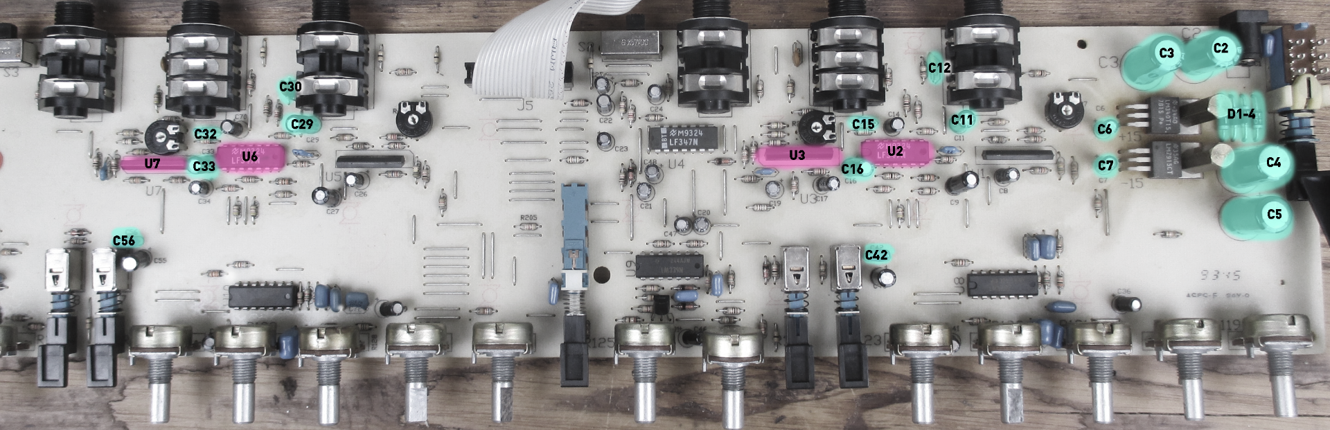
Component Location Guide
Here's a picture with everything we are changing marked and labelled. Active components are in pink, and passive components in green. Click the image to see it full size.
Remove Components
Remove ICs
Locate the ICs at positions U2, U3, U6, & U7. They are highlighted in pink in the above photo. There are a number of ways to remove the ICs (indeeed, there are a number of ways to do most things).
The easiest way is to clip the chips' pins as close as possible to the top of the PCB, and then use a desoldering wick or a solder sucker to clear each pin of solder. Then, if they haven't already just fallen out, pull the pins out with some needle-nose pliers. You shouldn't have to pull hard at all to remove the pins. If you find yourself pulling because a pin is stuck, odds are there is still some solder connecting the pin to the pad. In that case give it another pass with your favored desoldering method.
Remove Passive Components
Next remove the passive components. Desolder the leads of the following components on the PCB and remove them from the board:
| Board Location | Value |
|---|---|
| C2, C3 | 1000uf 16V |
| C4, C5 | 1000uf 25V |
| C6, C7 | 4.7uf |
| C11, C29 | 22uf |
| C12, C30 | 150pf |
| C16, C33 | 10uf |
| C15, C32 | 50pf |
| D1-D4 | UF4001 |
Install ICs

Install IC Sockets
Put the single-row sockets (that came in the bag with the ICs) in positions U3 and U7.
In positions U2 and U6, place the dual-row socket, being sure that the notch in the dual-row socket corresponds with the drawing on the PCB. (The single row sockets are unmarked which means when placing the IC in the socket you'd have to align the IC with the drawing on the PCB.)
Tape each of these snugly to the top of the PCB, then flip the board over and solder them in place.

Install ICs
After you've soldered the sockets in place, insert the ICs into their various sockets. Be sure the dots on the ICs are on the same side as the notches on the sockets and the notches on the PCB silk-screen.
| Board Location | Value |
|---|---|
| U3, U7 | 2180BL08-U |
| U2, U6 | TL084IN |
Install Passive Components

Install Diodes
Put the leads of the diodes through the holes on the top of the PCB and then bend them on the underside of the PCB so they hold tight in place. Be sure that the gray stripes on the diodes line up with the striped graphic on the PCB. This is important.
| Board Location | Value |
|---|---|
| D1-D4 | UF4001 |

Install Electrolytic Capacitors
The electrolytic capacitors are polar, meaning (among other things) that they only work one way. On each capacitor there is a gray stripe with minus signs in it: this is the negative terminal. So be sure that the opposite terminal gets inserted into the hole marked with a plus sign. Insert the various capacitors into the top of the PCB and bend the legs on the bottom to hold them fast to the PCB. Then flip the board over, solder them, and trim their leads.
| Board Location | Value |
|---|---|
| C2, C3, C4, C5 | 2200uf 25V |
| C6, C7 | 4.7uf |
| C11, C29 | 22uf |
| C16, C33 | 10uf |

Install Silver Mica Capacitor.
This part's a little tricky, because it turns out the best-sounding 150pF capacitor we could find doesn't quite fit through the PCB through-holes. The legs of the caps for C12 and C30 are a bit too thick, so you'll have to trim them down solder discarded leads from one of the other caps. This is the method I used (requires at least needle nose pliers):
1. Secure the capacitor, with something other than your hands (cause you will need both of them) so that the leads are up in the air.2. Tin the tip of the soldering iron with a bit of extra solder.
3. With a pair of pliers, hold the new lead up to lead of the mica cap.
4. Touch the tinned soldering iron to the two legs till the solder joins them
5. Remove the iron and let the solder solidify
| Board Location | Value |
|---|---|
| C12, C30 | 150pf |
| C15, C32 | 22pf |
Optional Mods

Disable the gates
If you'd like to disable the gates on your 3630 all you have to do is snip the two wires in yellow boxes. That's all there is to it. Disabling the gates will slightly lower the noise floor of the entire unit.
Adjust the time constants
To adjust the tighten up the attack/release of the 3630 you can replace 100nF capacitor at the locations C42 and C56 with 10nF capacitors.
| Board Location | Value |
|---|---|
| C42, C56 | 10nF |