FE2 Version 1 XLR Jack Assembly
If you purchased your FE2 kit before 5.26.2016, follow the instructions for mounting the XLR jack below, then return to the rest of the guide.
Soldering the XLR jack is the only truly tricky part of the build and requires a little patience and care. This is because we need to do a bit of point-to-point wiring and "surgery" on the XLR jack to insure the grounding is ideal.

Screw Panel to Jack
Screw the XLR jack to the output panel via the bottom screw hole.

Wrap Ground Wire
Remove the plastic insulation from one end of the black hookup wire. Wrap this end around the ground tab of the XLR jack, about halfway up the body of the jack. If you solder it too close to the panel, the wire won't stretch as far as we need it to go.

Solder Wire to Jack
Solder the wire to the ground tab.

Cut XLR Ground Tab
Once the solder has cooled, cut the ground tab at the corner to disconnect pin 1 from the ground tab. Be very careful not to pull the remaining tab away from the plastic.
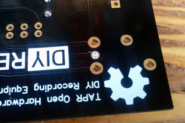
Solder Middle XLR Pad
It's rather difficult to get the PCB to sit on top of the XLR jack long enough to solder it. So we'll take a different approach: adding solder to the PCB first and then heating that solder while inserting the jack. To start, add a small amount of solder to the middle pad of the XLR footprint.
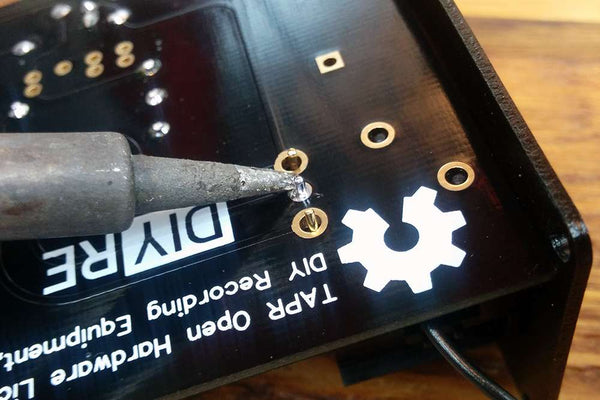
Insert XLR While Heating
Now comes the semi-tricky part: reheat the middle pad while pushing the XLR jack up into the PCB from underneath. Once the solder melts, the XLR jack will slide easily into place. Remove your iron and allow the joint to cool while holding the XLR jack in place.

Solder XLR
Now solder the other two pins of the XLR jack. Once they've cooled, add a bit more solder to the middle pin if necessary. Do not solder the plastic pins.

Tin Ground Wire
Remove the insulation from the remaining end of the hookup wire. Now "tin" the tip by heating it and adding a bit of solder. This will prevent the wire from fraying in the next step.

Solder Wire to PCB
Bend the wire around the outside of the jack (needle-noise pliers can make this a bit easier if you have them on-hand) and place the tinned end in the "Gnd" pad. Solder the wire to the Gnd pad and trim the excess.
Return to the rest of the FE2 Assembly Guide (resume at step 4.1).