JFT Assembly Guide
Damaged or Missing Parts All kits and parts are checked before being shipped to you. If something arrives damaged or if your kit is missing a part, please open a support ticket to inquire about a replacement. Missing parts will be replaced at our expense. Damaged parts should be returned for verification. If the part shows signs of use beyond what was necessary to determine that it was damaged, DIY Recording Equipment, LLC reserves the right not to replace the part.

Thank you for purchasing a !
If this is your first DIY project ever, we recommend reading our Getting Started Guide.

Required Tools
You'll need the tools below to complete this build.

Soldering Iron
We recommend an adjustable-temperature station, such as the $40 Weller WLC100.

Solder
You can use 60/40 "leaded" solder or lead-free. We recommend 60/40 because it flows better and is easier for beginners to use.
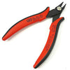
Wire Cutters
You'll need a pair of good "snips" for cutting of the excess leads after soldering.
Optional Tools
These tools aren't strictly necessary but can make your build a bit easier.

Multi-Meter
If you find the color bands on resistors a bit hard to read, you can use a meter to sort them with absolute confidence.
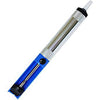
Desoldering Pump
If you accidentally solder something in the wrong place, a desoldering pump can save the day.
0. Resistor Calculator
Type in the value of the resistor you need and this tool will show you the corresponding color code.
Check Revision
This assembly guide is for mkI of the JFT, which was discontinued in 2019. If you bought your kit after 2019, go to the new JFT assembly guide.
Place Connectors
Identify and Sort Components


Insert Stand Offs and Connector
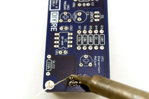
Solder Connector
Place Resistors

Insert and Bend Resistor Leads

Solder Resistors

Trim Resistor Leads
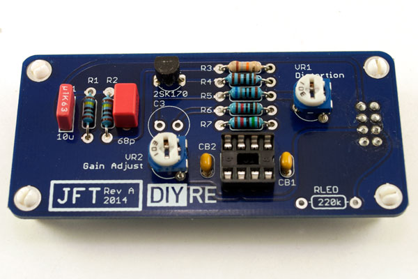
Place Larger Components

Capacitors, Transistor and IC Socket
Trim Potentiometers

Electrolytic Capacitor

Insert IC
Calibrate and Check
Distortion and Gain Adjustments
Don't Panic: The steps below require you to adjust a component on the JFT board while the circuit is powered up and working. If you accidentally touch the wrong components with the screw driver, it may damage your JFT, Palette, or even 500-series rack. Take a deep breath, keep a steady hand, and enjoy the experience. This is real DIY, my friend!
No two of the transistors used in the JFT are exactly alike. So to make them behave the way we want, we've got to adjust their surrounding environment a bit. This requires a screw driver, audio interface, and the most sophisticated test equipment known to humankind: your ears.
Plug your assembled JFT into your assembled and tested Palette, turn it on, and connect it to your mixing setup so that you can send signals to your Colour and monitor its output. Send some typical program material to your Colour channel--acoustic guitar and piano tracks work well, but you will surely want to try various sources. Simply assign the track to the output your Colour is plugged into and set the track's fader at its default level. If your interface includes a volume control for the line outputs, set the control to unity gain, sometimes marked as "line" or "+4dBu."
Now play with the front panel controls and the JFT's distortion trim until it sounds like the tool you want it to be. What we're going for here is to set the JFT trim where the unit is most useful and inspiring to you for a range of program materials and Colour settings. Your ears will make the final decision, but here are some general guidelines:
- With the Colour control turned all the way down, distortion should be practically unnoticeable.
- With Colour turned all the way up, distortion should be clearly audible, if not crunchy and agressive.
- With Colour set to the longer line that leads to the LED on the front panel, distortion should register as an "enhancement" of the original signal. That is, it it heard as "warmth" or "color" rather than distortion.
You will most likely need to go back and forth between the gain and distortion trimmers several times before finding the sweet spot. For the final gain trim, turn the Saturation down all the way and push the JFT bypass/engage switch every few seconds. Adjust the trim until you do not hear a difference in volume between having the JFT engaged and bypassed.
Final Checks
Before you wrap up, check the following things:
-
Capacitor orientation: Is the stripe on the cap on the opposite side from the "+" marking on the PCB?
-
IC orientation: Does the dot/notch on the IC align with the notches on the socket and PCB?
-
Transistor orientation: Does the shape of the transistor match the outline on the PCB?
-
Resistors: Do all of the resistor positions correspond the chart and/or sorting sheet?
-
Soldering: Is every solder joint shiny and clean? If one is cloudy or misshapen, try reheating it for 8 seconds and adding a tiny bit more solder.
-
Trimming: Are all of the excess leads trimmed down as close to the joint as possible?
All good? Congrats on finishing your build! Have a question or problem? Drop us a line.
Help Us Improve
1
2
3
4
5
6
7
8
9
10