Passive Pickup Emulator (PPE) Assembly Guide
Safety Precautions, Warranty, and Disclaimer Improper soldering and handling of electricity can cause serious injury and damage to your property. Read and understand the instructions below before beginning your project. Follow the instructions, build carefully, and use the appropriate tools. Build at your own risk. DIY Recording Equipment, LLC is not responsible for any damage or injury resulting from the assembly or use of your PPE kit. You are the manufacturer of your PPE. It is your responsibility to turn this group of parts into a working piece of recording equipment. DIY Recording Equipment, LLC does not guarantee the success of your project and disclaims any Implied Warranty of Merchantability. Please visit the support forum for assembly support. Damaged or Missing Parts All kits and parts are checked before being shipped to you. If something arrives damaged or if your kit is missing a part, please contact me directly via this contact form to inquire about a replacement. Missing parts will be replaced at my expense. Damaged parts should be returned to me for verification. If the part shows signs of use beyond what was necessary to determine that it was damaged, DIY Recording Equipment, LLC reserves the right not to replace the part.
Required Tools
It's quite possible to complete the PPE with only the tools pictured. If this is your first DIY project, please see the Getting Started Page for beginner tips and recommended tools.
Optional Tools
A multi-meter and desoldering tool are essential for troubleshooting and replacing faulty or misplaced components. A "helping hands" tool is great for magnifying and stabilizing your work surface.
1
Let's get started! Bend the leads of the 15k resistor (R1) as shown and remove the capacitor (C1) from its packaging. You will find two small ceramic capacitors in your kit. The one marked "104" has a value of .1uF and will yield a darker "early Strat" sound. The cap marked "223" has a value of .022uF and will yield a brighter, more modern tone.
2
Insert R1 and C1 through the top of the PCB and bend their leads so that they'll stay in place when the board is flipped over.
3
Solder the components to the PCB and trim their leads just above the solder joint. For an excellent introduction on how to solder see this video from Sparkfun.
4
Snap the metal tab off of the potentiometer with pliers and remove all of the nuts and washers from the bypass switch in preparation for mounting them in the chassis.
5
Mount the pot and switch in their respective holes in the case and place the PCB onto their leads with the component side facing up. Solder the pot to the PCB, leaving the switch unsoldered. Remove the PCB and switch from the case.
6
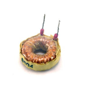
Trim the inductor leads down to about 1/2" (13mm) and strip the wires, leaving only about 1/8" (3mm) of insulation. If the insulation is left too long, the inductor will not fit inside the case.
7
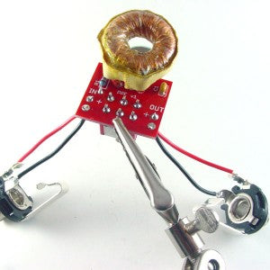
Insert the inductor into the L1 pads with the coil oriented over the pot. Flip the board over, solder, and trim the leads.
8
Insert the switch into the SW1 pads from the bottom of the PCB. Solder the switch leads to the top of the PCB.
9
Cut two 2" (5cm) lengths each of red and black wire. Strip the ends, leaving about 1/4" (6mm) bare on each end and "tin" the tips by applying a small amount of solder.
10
Insert the wires into the pins of the jacks. Bend the tinned ends of wire around the pins to form a solid mechanical connection before soldering. Solder the wires to the jacks, soldering the black wire to the inner, "sleeve" pin and the red wire to the outer, "tip" pin.
11
Solder the remaining ends of the hookup wire to the PCB, making sure to solder the red wires to the pads marked "+."
12
Assembled the completed PCB and jacks in the chassis, making sure that the metal pins of the jacks do not touch the sides of the chassis.
The end.
Your PPE is complete! Go make some beautiful noise by plugging the output of a reamping box, synthesizer, keyboard, active guitar pickup, etc. in the input jack (on the right) and patching the output (on the left) into any guitar-level gear you please. Keep the toggle to the left to keep the effect engaged, or switch it to the right to bypass the PPE completely. The potentiometer behaves exactly like an early-Fender tone control. If you're PPE doesn't work or you have questions about how it works, please visit the Support Forum.


