PR502 1.1 Assembly Guide
Damaged or Missing Parts All kits and parts are checked before being shipped to you. If something arrives damaged or if your kit is missing a part, please open a support ticket to inquire about a replacement. Missing parts will be replaced at our expense. Damaged parts should be returned for verification. If the part shows signs of use beyond what was necessary to determine that it was damaged, DIY Recording Equipment, LLC reserves the right not to replace the part.

Thank you for purchasing a PR502 2-Slot 500-Series Chassis Kit with External Power Supply!
If this is your first DIY project ever, we recommend reading our Getting Started Guide.

Required Tools
You'll need the tools below to complete this build.

Soldering Iron
We recommend an adjustable-temperature station, such as the $40 Weller WLC100.

Solder
You can use 60/40 "leaded" solder or lead-free. We recommend 60/40 because it flows better and is easier for beginners to use.
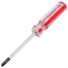
Phillips Head Screwdriver
A #1 Phillips head screwdriver.

Flat Head Srewdriver
A small flat head screwdriver.
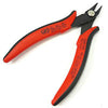
Wire Cutters
You'll need a pair of good "snips" for cutting of the excess leads after soldering.
Optional Tools
These tools aren't strictly necessary but can make your build a bit easier.

Wire Strippers
Removing the insulation from wires with regular wire cutters can be a fiddly, frustrating job. But dedicated wire strippers make it a breeze.

Tape
A bit of clear tape will help hold some tricky components in place for soldering.

Multi-Meter
If you find the color bands on resistors a bit hard to read, you can use a meter to sort them with absolute confidence.
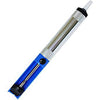
Desoldering Pump
If you accidentally solder something in the wrong place, a desoldering pump can save the day.
0. Resistor Calculator
Type in the value of the resistor you need and this tool will show you the corresponding color code.
Diodes

Sort Bag 1
Sort the bags of diodes using the component sorting sheet (PDF). The three types orange diodes look very similar, so we placed them in separate bags. Make sure not to mix them up!

Bend and Place Diodes
Bend the diodes' leads so that they'll fit into the holes on the PCB, then place them in their respective places. As you place each diode, bend the leads against the bottom of the PCB to hold it in place.
Polarity: All of these diodes must be placed in a certain orientation, which is indicated by a stripe on the body. Make sure to line up the stripes on the diodes with the stripes on the PCB.
Solder Diodes
Make sure your soldering top clean and tinned with a bit of solder. Then follow the 8-second soldering rule of thumb: heat the joint for 3 seconds, add solder for 2 seconds, the keep heading for another 3 seconds.

Trim Excess Leads
Cut the leads down as close to the solder joints as possible, without clipping the joints themselves.
Resistors

Sort Bag 2
Sort the resistors using the "Easy Resistor Sorting" tool above or a multi-meter. Component sorting sheet (PDF).

Place and Solder Resistors
Place the resistors in their respective places, solder, and trim.
Capacitors, LEDs, and Power Resistors

Sort Bag 3
As you sort the power resistors, remove the tape from their leads. Component sorting sheet (PDF).

Place Small Capacitors
Place the small, orange capacitors C3 and C4. These caps are not polarized, so orientation doesn't matter.

Insert LEDs
Insert LEDS 1-3 as far as the flat part of the leads.
Polarity: Place the longer lead in the "+" hole.

Bend and Solder LEDs
Bend the LEDs forward to where the rear panel will be, then solder and trim.

Place Power Resistors
Place the R1 and R2 resistors. Leave about 1/4" space between the resistors and the PCB, as these parts will give off significant heat.

Place LINK Header
Place the 2-pin, LINK header with the longer leads facing up. Then place the 2-pin shunt over the pins and solder. You may need to use a piece of tape to hold the header in place for soldering.

Place Large Caps
Place the larger, electrolytic capacitors.
Jacks and Switches


Install Switch Caps
Press the caps onto the switches until they snap in completely.

Place Switches
Places the switches and use a small screwdriver to bend a couple of the leads against the bottom of the PCB. Solder and trim.

Place Jacks
Place the XLR jacks. Most will snap in place, but you may need to use some tape to hold the 5-pin jacks in place. Solder the jacks but do not trim the leads.
Transistors

Place Transistors
Place the transistors Q1 and Q2. It's very important that these are placed in the correct position and orientation! Solder the transistors and trim the excess leads.
Polarity: Place the transistors so that the "TIP2955"/"TIP3055" text is facing the "2955"/"3055" text on the PCB.

Install Heatsinks
Place the heatsinks in the PCB and fasten them to the transitors. Place the lock washers between the nuts and the back of the heatsinks.

Place Standoff
Place the long screw through the bottom of the PCB, then thread the two standoffs onto it from the top.
Card Edge Connectors


Place Right-Angle Headers
Place the right-angle headers through the bottom of the PCB so that the longer pins are pointing out towards where the front panel will be, then solder.

Install L-Brackets
It may be hard to see, but one end of the L-brackets is longer than the other. Fasten the longer end to the PCB via the short, silver screws.

Place Card Edge Connector
Fasten the card edge connector to the card edge PCB with some tape, then solder and trim the leads.

Attach Card Edge Board to Motherboard
Use the longer, black screws to fasten the card edge PCB to the motherboard. Then solder and trim the longer leads of the right-angle headers.
Tip: When the switches are in the out position, you can rest the whole assembly on the jacks and switches.
Chassis


Attach Rear Panel
Screw the rear panel to the XLR jacks. Place the lock washers on the lower screw hole of each jack.

Attach Side Panels
Screw the side panels to the rear panel using the shorter, pan head screws.

Insert Top and Bottom Panels
Slide the top and bottom panels into the channels in the side panel. Orient them so that the vents are near the rear panel.

Attach Front Panel
Screw in the front panel using the remaining flat head screws.

Chassis Complete
Nice job! Please perform the checks in step 8.8 below, then you can start plugging stuff in and using your 500-series modules! If you purchased the extender cable, see the steps below for assembly.
If you had any troubles with your build, feel free to drop us a line on our Support Page.
Extender Cable

Disassemble XLR Plugs
Unscrew the XLR plugs and separate the parts. Make sure to keep the parts for the male and female plugs separate.

Place Plug Bottoms of Cable
Place the bottom parts of both plugs over the cable. This is very important—if you solder the plugs before placing these on the cable you'll have to desolder and start over!

Cut Insulation
Use wire cutters to cut the gray insulation around the cable. Make sure not to cut any of the wires in the cable.

Remove Insulation
Remove about 1" (25mm) of insulation from each end of the cable.

Remove Insulation from Wires
Use wire strippers to remove about 1/4" (6mm) of insulation from each wire.

Tin Wires
Tin each wire by heating it and then adding a bit of solder. Tin the whole length of the silver wire with no insulation.

Assemble Plugs
Final Checks
Before you wrap up, check the following things:
-
Capacitor orientation: Is the stripe on the cap on the opposite side from the "+" marking on the PCB?
-
Transistor orientation: Does the shape of the transistor match the outline on the PCB?
-
Diode orientation: Do the stripes on the diode match those on the PCB?
-
Resistors: Do all of the resistor positions correspond the chart and/or sorting sheet?
-
Soldering: Is every solder joint shiny and clean? If one is cloudy or misshapen, try reheating it for 8 seconds and adding a tiny bit more solder.
-
Trimming: Are all of the excess leads trimmed down as close to the joint as possible?
All good? Congrats on finishing your build! Have a question or problem? Drop us a line.
Help Us Improve
1
2
3
4
5
6
7
8
9
10