RED-25 Assembly Guide
Damaged or Missing Parts All kits and parts are checked before being shipped to you. If something arrives damaged or if your kit is missing a part, please open a support ticket to inquire about a replacement. Missing parts will be replaced at our expense. Damaged parts should be returned for verification. If the part shows signs of use beyond what was necessary to determine that it was damaged, DIY Recording Equipment, LLC reserves the right not to replace the part.

Thank you for purchasing a RED-25 Discrete Opamp!
If this is your first DIY project ever, we recommend reading our Getting Started Guide.

Required Tools
You'll need the tools below to complete this build.

Soldering Iron
We recommend an adjustable-temperature station, such as the $40 Weller WLC100.

Solder
You can use 60/40 "leaded" solder or lead-free. We recommend 60/40 because it flows better and is easier for beginners to use.
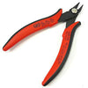
Wire Cutters
You'll need a pair of good "snips" for cutting of the excess leads after soldering.
Optional Tools
These tools aren't strictly necessary but can make your build a bit easier.

Multi-Meter
If you find the color bands on resistors a bit hard to read, you can use a meter to sort them with absolute confidence.
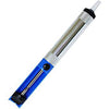
Desoldering Pump
If you accidentally solder something in the wrong place, a desoldering pump can save the day.
Assemble PCB

Identify Parts
Open up the parts bag and identify the parts. From left to right they are:
- 5x DOA Pins
- 2x Resistors
- 2x Input transistors (BC550C)
- 2x Power transistors (BD139, BD140)
- 1x Circuit board
Pay special attention to the BD139 and BD140 transistors. Although they are the same shape, they are two different parts that will go in different positions in step 1.7.

Place Pins in Sockets
Keeping the pins in place for soldering can be tricky, but luckily you've (probably) already got the perfect jig to hold them. Place the pins in the sockets of a piece of gear that accepts a DOA, such as the DOA Colour pictured. Make sure to insert the pins until they snap in, but do not solder them! Also note that the RED-25 does not have a 6th ground pin.

Solder Pins
Place the RED-25 circuit board over the pins and solder. Wait 30 seconds between soldering each pin so that the previous joint can dry. Once all the pins are soldered, remove the assembly from the sockets.

Place Resistors
Bend the leads of the resistors and place them in the R11 and R12 positions. The resistors are not polarized and can be placed in any orientation. Both resistors are the same value. After you've placed them, bend their leads against the bottom of the circuit board.

Solder and Trim Resistors
Solder the resistors and trim the excess leads. Trim the leads down as close to the solder joint as possible without clipping the joints themselves.
Place and Solder Q1 and Q2
Place the smaller transistors in the Q1 and Q2 positions. Make sure to orient the transistors according to the outlines on the circuit board. As you did with the resistors, bend the leads against the bottom of the PCB, solder, and trim.
Place and Solder Q7 and Q8
Notice: Even if you skim the rest of the guide, pay attention to this step! Q7 and Q8 are two different transistors that must be placed in the correct positions: BD139 in Q7 and BD140 in Q8.
Place the BD139 transistor in Q7 and the BD140 transistor in Q8. Place them both with the text side facing the Q1 and Q2. Now double check:
- Is BD139 in Q7?
- Is BD140 in Q8?
- Are the sides with text facing Q1 and Q2 (away from the resistors)?
Once you're sure the transistors are in the correct positions and orientation, solder and trim the leads.
Final Checks
Before you wrap up, check the following things:
-
Transistor orientation: Does the shape of the transistor match the outline on the PCB?
-
Soldering: Is every solder joint shiny and clean? If one is cloudy or misshapen, try reheating it for 8 seconds and adding a tiny bit more solder.
-
Trimming: Are all of the excess leads trimmed down as close to the joint as possible?
All good? Congrats on finishing your build! Have a question or problem? Drop us a line.
Help Us Improve
1
2
3
4
5
6
7
8
9
10