Tone Cube Assembly Guide
Thank you for purchasing a Tone Cube kit! The assembly instructions below are for the Woodworker's kit, which comes un-assembled, un-finished, and without a driver. Full kit instructions will follow as we continue to develop the kit.Required Tools and Skills
Successfully completing the Tone Cube Woodworker's kit requires several standard woodworking and electronics tools, moderate woodworking experience, and some soldering experience. The tools required are:- Jig saw
- Drill
- Screw driver
- Wood clamps (at least two)
- Wood glue
- Drafting compass and pencil
- Soldering iron and solder
- Wire cutter/stripper
- Needle-nose pliers
Recommended Drivers
The Woodworker's kit allows you to choose your own speaker drivers. The table below lists the drivers we're aware of that meet the rough specifications of the 5C sound and are available off-the-shelf. We expect this list to grow as more builders source their own drivers and provide feedback. If you know of a suitable driver we're missing here, please let us know in the comments. Thanks!| Manufacturer | Part # | Details | Freq Response | Available From | Price |
|---|---|---|---|---|---|
| Grand Audio HK | L69AW | 5", shielded | 45-10k | Maplin (UK only) | £9.99 |
| Goldwood | GW-2058 | 5.25", shielded | 92-9k | All Electronics | $12.30 |
| Visaton | FR12 2061 | 5.31", unshielded | 70-18k | MCM Electronics | $13.99 |
| Celestion | 299-416 | 5", unshielded | 104-9K | Parts Express | $18.74 |
Assembly Guide

1
Begin by preparing the blank driver panel for the driver of your choice. Measure your driver to determine the required radius of the cutout hole. Set your compass to this radius and draw a guide circle. Use the provided guide hole to center your compass on the driver panel.

2
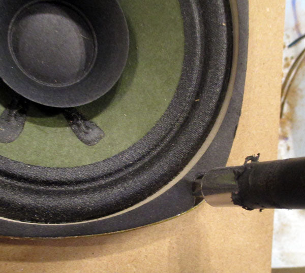
Drill a hole on the inside of your guide line big enough to insert your jig saw. At this stage, it is better to err on the side of making your driver hole slightly too small. You can always take more material away, but you can't put it back! In order to preserve your work surface, locate a piece of scrap wood or foam on which to operate the jig saw. To prevent the panel from flying across the room while you are cutting, clamp both your scrap piece and the panel to your work surface.

3
Now cut the driver hole. If you do not feel comfortable using a jig saw on the panel yet, practice on a piece of scrap wood first and test with your driver.

4
Place your driver in the hole and and mark the location of the driver's mounting holes with a marker or pencil.
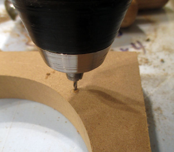
5
Remove the driver from the hole and drill pilot holes for the mounting screws. The bit for the pilot holes should be smaller than the diameter of the provided wood screws.

6
Practice putting the speaker cabinet together without glue to get an understanding of how everything should fit.

7
Apply glue to the inside corners of all the rabbited areas of the side panels. Lay the side panels around the connector panel.

8
Loosely assemble the sides and connector panel.

9
Place driver panel on top of the assembly and clamp the box together. If you have a limited supply of clamps. You can divide this process and glue two panels at a time using the terminal panel and driver panel as guides.

10
To ensure even pressure, place the clamps as close to the center of the box as possible. The panels will shift around as you place and tighten the clamps. Adjust the clamps until everything is even and then let the glue dry for at least 30 minutes.

11
While we wait for the wood glue to dry, let's fire up the soldering iron. Strip the ends of the hookup wire about 1/4" and tin them by applying a small amount of solder. This will make your life easier by keeping the wires from fraying when you insert them into the crimp terminals.

12
Solder one end of each wire to the crimp terminals. Let the solder cool for 30 seconds and then crimp the tabs around the wire with needle-nose pliers.

13
Solder the other ends of the wires to the terminals of your driver. Following convention, solder the red wire to the "hot" (+) and black wire to the "cold" (-) terminal.

14
Once the glue has dried, remove the clamps. If necessary, fill any gaps in the joins with glue and remove excess, dried glue with fine-grit sandpaper. You should do any painting or finishing you wish to do at this point. Once your box is finished to your liking, insert the fiberglass insulation through the driver cutout. Place the driver in the front panel and string the hookup wires under the fiberglass and through the connector hole. Slide the crimp terminals onto their respective terminals on the connector block (red -> +, black -> -) and place the connector in the back panel.
15
Screw the driver and connector in place with the included wood screws.
16
Finally, apply the foam insulation pad to the bottom of your speaker. Make sure the surface is clean and free of dust before applying the adhesive pad. The adhesive on the pad is very tacky, so apply with care!