EQP5 Assembly Guide
Damaged or Missing Parts All kits and parts are checked before being shipped to you. If something arrives damaged or if your kit is missing a part, please open a support ticket to inquire about a replacement. Missing parts will be replaced at our expense. Damaged parts should be returned for verification. If the part shows signs of use beyond what was necessary to determine that it was damaged, DIY Recording Equipment, LLC reserves the right not to replace the part.

Thank you for purchasing a EQP5 Passive Equalizer!
If this is your first DIY project ever, we recommend reading our Getting Started Guide.

Required Tools
You'll need the tools below to complete this build.

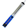
Soldering Iron
We recommend an adjustable-temperature station, such as the $40 Weller WLC100.

Solder
You can use 60/40 "leaded" solder or lead-free. We recommend 60/40 because it flows better and is easier for beginners to use.
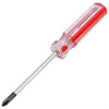
Phillips Head Screwdriver
A #1 Phillips head screwdriver.
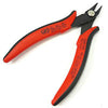
Wire Cutters
You'll need a pair of good "snips" for cutting of the excess leads after soldering.
Optional Tools
These tools aren't strictly necessary but can make your build a bit easier.

Tape
A bit of clear tape will help hold some tricky components in place for soldering.

Multi-Meter
If you find the color bands on resistors a bit hard to read, you can use a meter to sort them with absolute confidence.
Desoldering Pump
If you accidentally solder something in the wrong place, a desoldering pump can save the day.
0. Resistor Calculator
Type in the value of the resistor you need and this tool will show you the corresponding color code.
Place Resistors

Sort Bag 1
Print the Print the EQP5 Component Sorting Sheet (PDF) and sort the resistors. You can identify the resistors by their color code or with a multi-meter.

Bend and Place Resistors
Bend the resistor leads at the body and then insert them into their respective places on the PCB.

Bend Resistors Against PCB
Bend the leads of the resistors against the bottom of the PCB so that the resistors stay in place during soldering.

Solder Resistors
Now solder the resistors to the PCB. Observe good soldering technique: heat the pad and lead for 2-3 seconds, apply a small bit of solder, and continue to heat the pad for another 2-3 seconds. Allow each solder joint 10 seconds to cool before moving on to the next one. The finished joints should be shiny and should have just enough solder to cover the pad entirely.
Once all of the solder joints have cooled, use your clippers to trim away the excess leads. Your goal should be to clip as close as possible to the joint without clipping the joint itself.
Place Small Capacitors, Fuses
Sort Bag 2
Sort the small capacitors and fuses in bag 2.

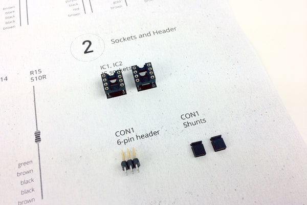
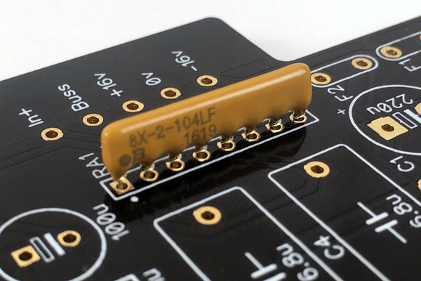
Place IC Sockets
Place the two 8-pin IC sockets in the IC1-IC2 positions on the PCB. Make sure to align the notch in the sockets' plastic with that one the PCB.

Bend and Solder IC Sockets
Use a flat-head screwdriver to bend two leads of each socket against the PCB. Then solder the sockets. There's no need to trim the excess leads.

Place 6-Pin Header
Place the 6-pin header in the CON1 position, then flip the PCB over and solder.

Place Jumpers on Header
Place the two solderless jumpers on the CON1 header to select between the Modern (IC) and Vintage (FE) outputs. For the Modern output, place the jumpers on the bottom rows of pins next to the "IC" label. For the Vintage output, place the jumpers on the upper rows next to the "FE" label.
Place Small Capacitors

Sort Bag 3

Place C5 and C8
As you did with the resistors, place, bend, solder, and trim the small capacitors.
FAQ: Are these parts polarized? Nope, insert them any way you like.
Place RA1
Place the 100k resistor array in the RA1 position. The orientation of the arrays does not matter.

Place VR5
Place the trim pot in the VR5 position. This is the bandwidth control for the HF+ band.

Place the Rest of Bag 3
Place and solder the remaining parts in bag 3.
LED Polarity: Make sure to place the longer lead of the LEDs into the "+" hole.
Place Filter Capacitors

Sort Bag 4
Quick Question
Place C7
Note that this must be inserted in the PCB in a certain direction. Like the LEDs, the longer lead indicates the positive terminal. Taking care to place the longer lead closer to the "+" marking on the PCB.
Once you've double checked the orientation, bend, solder, and trim.

Populate C15 and C16
Place the capacitors C15 and C16. The dashed capacitor footprints next to them are for customizing the frequency bands. If you are building the stock kit, you can ignore these footprints.

Place Film Capacitors
Place the remaining capacitors in bag 4.

Place Fuses
Insert the fuses F1 and F2 just up to where the leads begin to kink. Then solder and trim.
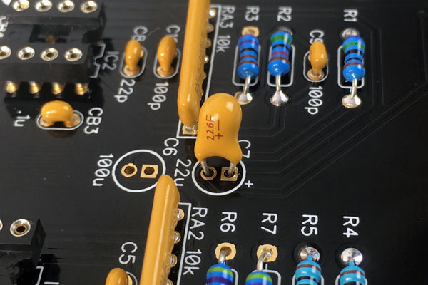
Large Capacitors

Place Electrolytic Capacitors
Polarity: Place the longer leads into the "+" hole. All of the capacitors should face the same direction.

Place Inductor and Large Film Caps
Place the inductor in the L1 positon and the large, film caps in C3 and C4. These parts are not polarized.
Place Potentiometers

Sort Bag 6

Place Mounting Brackets
Flip the PCB over and insert the brackets from the bottom of the PCB. Solder them, but do not trim the leads.

Place Potentiometers
Place the potentiometers in positions VR1-VR4. Pay close attention to the values marked on the back! Each pot has a different value and must be matched with the value on the PCB. Bend two leads of each pot against the PCB, then solder and trim.

Place Daughterboard (DB) Sockets
Place the sockets in the CON2A and CON3A positions. Bend some leads to hold them in place, then solder and trim.

Insert Standoffs
Loosely screw in the two standoffs from below the PCB.
Place Daughterboard Parts

Sort Bag 7

Place DB Brackets
Place the remaining brackets through the top of the PCB and solder.

Place Switches
Place the switches in SW1-SW5 positions. Bend two leads of each to hold them in place. Then solder them and trim the leads.

Place LED3
Place the LED in the LED3 position on the bottom of the motherboard PCB. Make sure to place the longer, positive lead in the "+" hole. Notice that the leads have a flat segment about 1/4" from the LED body. Insert the LED until the bottom of this flat segment, then bend it towards where the front panel will be, solder it in place, and trim the leads.

Attach DB
Place the 12-pin headers in the CON2A, CON3A sockets, making sure to place the sides with longer leads in the sockets. Then place the daughterboard over the short end of the header and screw it to the standoffs. Press the headers up so that the black, plastic square-posts are flush with the bottom of the DB. Then solder the headers to the top of the DB.
Place Integrated Circuits

Sort Bag 8

Place ICs
Place the ICs in their respective sockets. You may need to bend their leads inward a bit for them to sit nicely. Make sure to align the notches or circles on the bodies of the ICs with those on the sockets and PCB silk-screen.
Front Panel Hardware

Sort Bag 9
Note there are five front panel screws in the kit, but only four needed. We throw in an extra because they have a tendency to get lost!

Attach Front Panel
Using the included hex wrench, screw the front panel onto the PCB assembly via the four mounting brackets.

Fasten Switch Caps and Nuts
Press the caps onto the switches and fasten washers and nuts over the pots.

Attach Knobs
Turn all of the pot shafts to the 12 o'clock position (10 detents from full CW or CCW). Now place the knob over the shaft so that the white indicator line points to the middle of the top position. Then fasten the knob with the included hex wrench.
Optional Mods
Add the Vintage Output Option
For more classic coloration, add the Vintage Output to your EQP5. If you've already purchased the Vintage Output, you can proceed to the assembly guide.
Choose Custom Frequencies
You can modify the frequency bands by changing capacitors. See the EQP5 Alternative Frequencies Mods for exact values.
Final Checks
Before you wrap up, check the following things:
-
Capacitor orientation: Is the stripe on the cap on the opposite side from the "+" marking on the PCB?
-
IC orientation: Does the dot/notch on the IC align with the notches on the socket and PCB?
-
Resistors: Do all of the resistor positions correspond the chart and/or sorting sheet?
-
Soldering: Is every solder joint shiny and clean? If one is cloudy or misshapen, try reheating it for 8 seconds and adding a tiny bit more solder.
-
Trimming: Are all of the excess leads trimmed down as close to the joint as possible?
All good? Congrats on finishing your build! Have a question or problem? Drop us a line.
Help Us Improve
1
2
3
4
5
6
7
8
9
10