Vintage Output Assembly Guide
Damaged or Missing Parts All kits and parts are checked before being shipped to you. If something arrives damaged or if your kit is missing a part, please open a support ticket to inquire about a replacement. Missing parts will be replaced at our expense. Damaged parts should be returned for verification. If the part shows signs of use beyond what was necessary to determine that it was damaged, DIY Recording Equipment, LLC reserves the right not to replace the part.

Thank you for purchasing a Vintage Output Bundle!
If this is your first DIY project ever, we recommend reading our Getting Started Guide.

Required Tools
You'll need the tools below to complete this build.

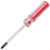
Soldering Iron
We recommend an adjustable-temperature station, such as the $40 Weller WLC100.

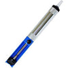
Solder
You can use 60/40 "leaded" solder or lead-free. We recommend 60/40 because it flows better and is easier for beginners to use.
Phillips Head Screwdriver
A #1 Phillips head screwdriver.
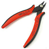
Wire Cutters
You'll need a pair of good "snips" for cutting of the excess leads after soldering.
Optional Tools
These tools aren't strictly necessary but can make your build a bit easier.

Tape
A bit of clear tape will help hold some tricky components in place for soldering.

Multi-Meter
If you find the color bands on resistors a bit hard to read, you can use a meter to sort them with absolute confidence.
Desoldering Pump
If you accidentally solder something in the wrong place, a desoldering pump can save the day.
Build the Stock Kit
This guide assumes that you have already built the stock EQP5 or OLA5 with the Modern output and whatever discrete opamp (DOA) you plan to use. If you haven't built your EQP5, OLA5, or DOA yet, follow that guide and the come back here!
Resistors and Capacitors

Solder Resistors and Small Cap
Identify the resistors via their color codes or my measuring them with a meter. Then place the resistors and small capacitor in their respective positions on the PCB. The capacitor is not polarized. Bend the leads against the PCB, solder, and trim.
Note that you will be have an extra resistor, as the EQP5 and OLA5 require different gain-setting resistors.
| Component | EQP5 | OLA5 |
|---|---|---|
| 100p Cap | C25 | C23 |
| 15k Resistor | R14 | R47 |
| 2.7k Resistor | R15 | X |
| 8.8k Resistor | X | R48 |

Solder Tantalum Capacitor
Locate the "+" text on the body of the large, tantalum capacitor. This indicates the positive lead of the cap. Place the cap with the positive lead next to the "+" on the PCB. Note that this capacitor may be either 220uF or 330uF.
Solder and trim.
DOA Sockets

Place DOA Sockets
Place the DOA sockets in the six plated holes of DOA1. Place tape over them to hold them in place during soldering.
Note: There is one extra socket in case you drop one.

Solder DOA Sockets
Solder the DOA sockets and remove the tape.
Transformer
Trim Leads
Trim the leads of the transformer down to about 1.5" (38mm). Be generous! You can always cut them shorter, but you can't make them longer after you've cut.
Then strip off about 1/8" (3mm) of the insulation and tin the leads by applying a bit of solder.
Place Transformer
Fasten the transformer in the X1 position with the included screws, nuts, and washers. Insert the screw through from the bottom of the PCB, then place the mounting parts over the screw in this order: plastic washers, transformer, lock washers, nuts.
Solder Transformer
Place the leads of the transformer through their respective holes (the GRY and VIO holes will remain empty) and bend the leads against the bottom of the PCB. Then flip the PCB over, solder, and trim.
Finishing Up

Place DOA
Place the DOA in the sockets. Push down until you feel the leads snap into place. If you purchased the RED-25, see the RED-25 Assembly Guide.

Move Jumpers
Move the jumpers on CON1 from "IC" (Modern) to "FE" (Vintage). You can change the jumpers back any time you want to use the Modern output.
Final Checks
Before you wrap up, check the following things:
-
Resistors: Do all of the resistor positions correspond the chart and/or sorting sheet?
-
Soldering: Is every solder joint shiny and clean? If one is cloudy or misshapen, try reheating it for 8 seconds and adding a tiny bit more solder.
-
Trimming: Are all of the excess leads trimmed down as close to the joint as possible?
All good? Congrats on finishing your build! Have a question or problem? Drop us a line.
Help Us Improve
1
2
3
4
5
6
7
8
9
10