FE2 Direct Box Assembly Guide
Damaged or Missing Parts All kits and parts are checked before being shipped to you. If something arrives damaged or if your kit is missing a part, please open a support ticket to inquire about a replacement. Missing parts will be replaced at our expense. Damaged parts should be returned for verification. If the part shows signs of use beyond what was necessary to determine that it was damaged, DIY Recording Equipment, LLC reserves the right not to replace the part.
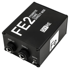
Thank you for purchasing a FE2 Direct Input Box Kit!
If this is your first DIY project ever, we recommend reading our Getting Started Guide.

Required Tools
You'll need the tools below to complete this build.

Soldering Iron
We recommend an adjustable-temperature station, such as the $40 Weller WLC100.

Solder
You can use 60/40 "leaded" solder or lead-free. We recommend 60/40 because it flows better and is easier for beginners to use.
Phillips Head Screwdriver
A #1 Phillips head screwdriver.
Wire Cutters
You'll need a pair of good "snips" for cutting of the excess leads after soldering.
Optional Tools
These tools aren't strictly necessary but can make your build a bit easier.

Multi-Meter
If you find the color bands on resistors a bit hard to read, you can use a meter to sort them with absolute confidence.
Desoldering Pump
If you accidentally solder something in the wrong place, a desoldering pump can save the day.
Assembly Video
Follow along with the assembly video or use the step-by-step guide below.
Populating PCB Components

Identify Resistors
The FE2 kit contains four resistors. Identify them by their color bands shown here.

Bend Resistors
Bend the resistors at their bodies so they'll fit easily into the PCB.

Place Resistors and Capacitor
Place the resistors in their respective places on the PCB. Place the capacitor in the area marked "C1."
Note: Since resistors don't have any polarity, it doesn't matter which way the leads are facing. And while capacitors often are polarized, the capacitor in C1 also has no polarity.

Bend Resistors and Cap Against PCB
Bend the leads of the resistors and cap against the bottom of the PCB so they stay in place during soldering.

Solder Resistors and Cap
Solder the resistors and cap to the PCB. Here are a few good soldering practices to observe:
- Heat the pad and lead together for 2-3 seconds before applying solder
- Apply just enough solder to cover the entirety of the pad, so that no gold is showing through
- Leave the iron in place while you are adding solder and for 1-2 seconds after
- The entire soldering process should take 5-8 seconds
- Allow the solder joint to cool for about 20 seconds before soldering another lead of the same component

Trim Resistors and Cap
Trim the excess leads as close to the solder joints as possible without clipping the joints themselves.

Place Switches and Bend Leads
Place the switches SW1 and SW2 and bend their leads to hold them in place. Then flip the PCB over, solder, and trim the leads.

Place Input Jacks
Place the TRS jacks in the J1 and J2 positions and remove their nuts and washers. To keep them in place, bend a few of their leads with the head of your screwdriver.

Bend Input Jacks
Solder the leads of the input jacks.
Placing Transformer
There are three transformer options for the FE2, each with different pinouts. Follow the placement instructions below for the transformer that came with you kit. Double (or triple!) check the position of your transformer before soldering! It's very difficult to remove a transformer after you've soldered it.

FE-X1
The FE-X1 belongs in the smallest transformer footprint marked "FE-X1." (On v1.0 of the PCB, the larger FE-X2 footprint is erroneously marked "FE-X1" as well.) Note a semi-circular notch on one corner of the transformer's plastic. Insert the pin nearest to this notch into the hole on the PCB surrounded by a white circle. Also, because the FE-X1 has only five pins, it's impossible to insert it incorrectly!

FE-X2
The FE-X2 belongs in the largest, square footprint marked "FE-X2" (or "FE-X1" on v1.0 of the PCB). Because it has seven pins, the FE-X2 can only be inserted in one direction.
Double check that the FE-X2 is not in the CM-DBX position. The FE-X2 should fit perfectly within the rounded, square box on the PCB and should not touch any resistors.
Place the FE-X2 sticker on top of the transformer as shown.

Cinemag CM-DBX
The CM-DBX belongs in the round transformer footprint marked "CM-DBX." Pin 1 is marked by a red dot on the underside of the transformer and a white dot on the PCB. Place the CM-DBX on the PCB so that these dots align.
Once you've confirmed that your transformer is in the correct position and orientation, solder it and trim the excess pins. To avoid damaging the transformer, wait 10-15 seconds between pins while soldering and do not heat any pin longer than eight seconds.
Placing XLR Jack

Cut XLR Ground Tab
Cut the ground tab on the back of the XLR jack with wire cutters and remove the loose portion of the tab.

Screw Panel to Jack
Locate the single long screw and place one of the tooth washers on it. Fasten the front panel to the XLR jack with the long screw and lock washer in the top XLR hole.

Solder Wire to PCB
Remove the insulation from one end of the black hook up wire. Place this end of the wire through the square pad labeled "Gnd" and solder it to the PCB.

Tin Ground Wire
Remove the insulation from the other end of the wire and bend it around a screw to make a hook shape. Now "tin" the wire by heating it as you would a component and adding some solder. This will prevent the wire from fraying when we screw it to the XLR jack later.
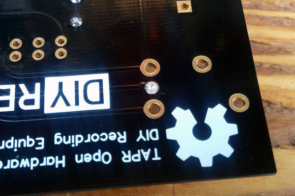
Solder Middle XLR Pad
It's rather difficult to get the PCB to sit on top of the XLR jack long enough to solder it. So we'll take a different approach: adding solder to the PCB first and then heating that solder while inserting the jack. To start, add a small amount of solder to the middle pad of the XLR footprint.
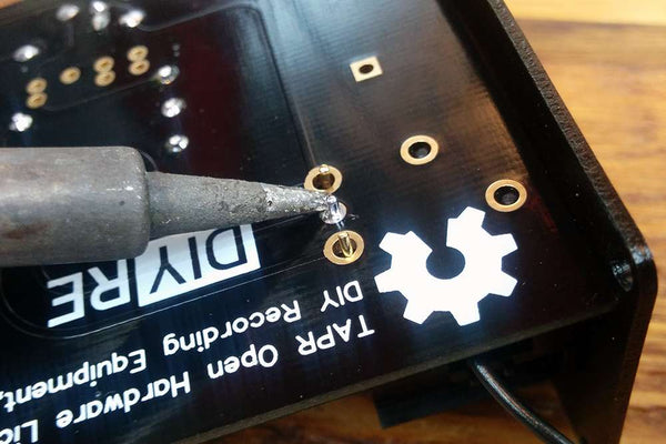
Insert XLR While Heating
Now comes the semi-tricky part: reheat the middle pad while pushing the XLR jack up into the PCB from underneath. Once the solder melts, the XLR jack will slide easily into place. Remove your iron and allow the joint to cool while holding the XLR jack in place.

Solder XLR
Now solder the other two pins of the XLR jack. Once they've cooled, add a bit more solder to the middle pin if necessary. Do not solder the plastic pins.

Screw Wire to Jack
Place the hook end of the black hookup wire around the top XLR screw. Then place the tooth washer and nut on the screw and tighten.
Final Assembly
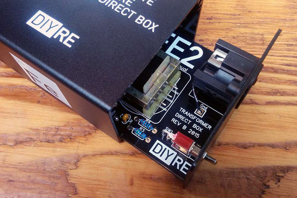
Slide PCB into Case
Slide the assembled PCB into the lower channel in the chassis. The output panel should be on the side of the case nearest the "2" in "FE2."

Screw in Panels
Screw in the remaining mounting screws. Since these screws are cutting their own threads in the aluminum, you'll feel a healthy amount of resistance the first time you put them in. It's a good idea to install all four screws on one panel loosely before tightening each one. If you have extra screws, that's ok! We always include extras in case you drop some.
After adding the panels, put the washer and nuts back on the input jacks.

Place Transformer Sticker
Place the sticker that came with your transformer on the blank side of the box.

Apply Foam Sticker
Remove the backing and apply the neoprene foam to the bottom of the case. Congrats on completing your build! If you're interested in learning more about how the FE2 works, check out our article How a Passive DI Works.
Final Checks
Before you wrap up, check the following things:
-
Resistors: Do all of the resistor positions correspond the chart and/or sorting sheet?
-
Soldering: Is every solder joint shiny and clean? If one is cloudy or misshapen, try reheating it for 8 seconds and adding a tiny bit more solder.
-
Trimming: Are all of the excess leads trimmed down as close to the joint as possible?
All good? Congrats on finishing your build! Have a question or problem? Drop us a line.
Help Us Improve
1
2
3
4
5
6
7
8
9
10