HC1 Headphone Amp Partial Kit Assembly Guide
Damaged or Missing Parts All kits and parts are checked before being shipped to you. If something arrives damaged or if your kit is missing a part, please open a support ticket to inquire about a replacement. Missing parts will be replaced at our expense. Damaged parts should be returned for verification. If the part shows signs of use beyond what was necessary to determine that it was damaged, DIY Recording Equipment, LLC reserves the right not to replace the part.

Thank you for purchasing a HC1 High Current Headphone Amp!
If this is your first DIY project ever, we recommend reading our Getting Started Guide.

Required Tools
You'll need the tools below to complete this build.

Soldering Iron
We recommend an adjustable-temperature station, such as the $40 Weller WLC100.

Solder
You can use 60/40 "leaded" solder or lead-free. We recommend 60/40 because it flows better and is easier for beginners to use.
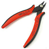
Wire Cutters
You'll need a pair of good "snips" for cutting of the excess leads after soldering.
Optional Tools
These tools aren't strictly necessary but can make your build a bit easier.

Multi-Meter
If you find the color bands on resistors a bit hard to read, you can use a meter to sort them with absolute confidence.
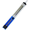
Desoldering Pump
If you accidentally solder something in the wrong place, a desoldering pump can save the day.

Print the Sorting Sheet
If you would like to sort components before placing them, download and print the HC1 Component Sorting Sheet (PDF).
Bag 1

Place Resistors
Sort and place the resistors in their respective positions. Bend their leads against the bottom of the PCB to hold them in place for soldering.

Solder and Trim Resistors
Solder the resistors and trim their leads as close as possible to the solder joints.
Bag 2

Place Ceramic Capacitors
Place and solder the ceramic capacitors CB1-CB4. These caps are not polarized.

Place IC Sockets
Place the IC sockets for IC1 and IC2 so that the notches align with the notches on the PCB silkscreen. Then solder them in place.

Place LED and Electrolytic Capacitors
Place the red LED and larger capacitors, paying close attention to their orientation. All of these parts are polarized; the longer lead is positive, while the negative lead on the capacitors is indicated by "-" markings on the body.
Bag 3

Place Potentiometer
Place the potentiometer VR1 and bend a few leads against the bottom of the PCB to hold it in place, then solder.

Place Connectors
Place and solder J1 and J2 first (since they are shorter) then the input jack J3.
Bag 4

Place ICs in Sockets
Place IC1 and IC2 in the sockets so that the notches on their bodies align with the notches in the sockets and on the PCB.
Power and Audio Inputs

Attach Power
You can power the HC1 with a 9v batter or DC power supply. Most "wall-wart" supplies will work fine. The HC1 with the stock opamps can accept between 9-44DC. If you substitute a different opamp, make sure to check the datasheet for its maximium power voltage.

Attach Audio Inputs
The HC1 takes unbalanced, line or consumer-level inputs. You can attach a single, unbalanced, stereo jack as shown, or two unbalanced mono jacks. If you use two mono jacks, run the ground (sleeve) wire from both into the "G" screw terminal so they are both connected to ground.

Go Wild!
Customize your headphone amp(s) for your set up. You can use hookup wire to daisy chain units to make a multi-channel headphone amp.
To mount the HC1 in a case, refer to the HC1 Dimensions sheet.
To power multiple channels, make sure your supply can provide enough current. Each HC1 draws up to 20mA. Multiply the number of channels by 20, then multiple the result by 1.5 to be safe. This is the total current your supply needs to be able to provide. For example, if you are building four-channel unit, your power supply should provide at least 120mA.
You can send a single audio output to up to four HC1s. Beyond this, the combined input impedance seen by the output will be too low.
Have fun customizing your headphone amp, and if you come up with something cool, please share it to our Facebook page.
Final Checks
Before you wrap up, check the following things:
-
Capacitor orientation: Is the stripe on the cap on the opposite side from the "+" marking on the PCB?
-
IC orientation: Does the dot/notch on the IC align with the notches on the socket and PCB?
-
Soldering: Is every solder joint shiny and clean? If one is cloudy or misshapen, try reheating it for 8 seconds and adding a tiny bit more solder.
-
Trimming: Are all of the excess leads trimmed down as close to the joint as possible?
All good? Congrats on finishing your build! Have a question or problem? Drop us a line.
Help Us Improve
1
2
3
4
5
6
7
8
9
10