How to Add L/C/R Switches to a Passive Summing Box June 25, 2012 15:28 7 Comments
The theory of operation is simple: instead of each input being hard wired to either the L or R bus, the inputs go first to a switch which then sends the signal to either a) the L or R buss or b) both buses (or "center"). The wiring, however, is not so simple. Assembling these switches requires considerable point-to-point wiring skill and a good deal of patience. The following guide assumes you have an Endless Summer kit, however the general method can be applied to your own passive summing project.

Components
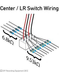
- Sort the 6.8k (blue, gray, black, brown, brown) and 9.53k (white, green, orange, brown, brown) resistors included in your kit. Each switch will use four 6.8k and eight 9.53k resistors.
- Trim two black and red pieces of hookup wire according to the distance between your switch and the jacks being switched, with a little extra length to account for the twisting. Strip and tin the ends of each wire.
Populating the Switch
- Place the hookup wires in the center row of pins, alternating black and red. Solder the wires to the pins and trim the leads. (Picture 1)
- Twist the pairs of hookup wires together tightly, leaving a 1/4" at the ends. (Picture 2)
- Place two 9.53k resistors in each pin of the bottom row so that the leads point out from the switch (away from the center row). Solder the resistors and trim the leads. (Picture 2)
- Do the same with the 6.8k resistors in the last remaining row of pins. Use only one resistor per pin. (Picture 3)
- Solder the hookup wires from the switch to the pins of the input jacks being switched. Solder the red wire to the Tip pin and the black wire to the Ring pin. (Picture 4)
Connecting the Switch to the Bus Wires
- Identify the two columns of pins associated with the each input jack. You will solder the 6.8k resistors from these columns to the bus wires that run directly above their respective jacks. Solder the resistor in the same column as the red wire to the "hot" bus wire and that in the black wire column to the "cold" bus wire. If you have already soldered the other, non-switching jacks to the bus wires, follow the standard you set regarding which wire is "hot" (Tip) and which is "cold" (Ring). Once you are done soldering, trim the leads. (Picture 1)
- Solder the 9.53k resistors in the same columns as a black wire to both of the "cold" bus wires and those in the red wire columns to both "hot" bus wires. At this point the wiring will become a bit of a rat's nest, and you may want to insulate the resistors from each other with the provided heat-shrink tubing. (Pictures 2, 3, 4)


Comments
max on November 12, 2014 18:02
very useful, thanks !!
Robb on November 12, 2014 18:02
Your mono switch instructions contradict your original instructions. In the main kit you have tip going to the bottom bus wire and ring going to the top. In the switches instructions you have the opposite occurring. I realize the mono switch was done later. Just wanted to post a heads up for others so they don’t have to re-do the switch section like I am having to do.
Peterson Goodwyn on November 12, 2014 18:02
Hi Robb, thanks for pointing that out. It had been about 10 months since I built the kit in the video, so I completely forgot what I did at the time.
Robb on November 12, 2014 18:02
No problem! Just wanted to point it out for others. I literally just finished my last solder on the kit! I am really excited to start analog summing!!!! Thanks for the putting together such a slick little kit!!! The little booklet that came with it was a nice touch! I have the DIY bug and and next am planning on doing a build of the Hairball/mnats Rev. f 1176 kits for about 6 people…the plan is I build 8 and keep 2. (my service fee for their builds) After that I am dying to build some pre’s and the Drip 670!!
Mark Gustafson on November 12, 2014 18:02
What kind of switch is used for this? I would like to add mono switches but cant find the proper switch as is shown. The closest thing I found was a 4PDT with on – on function. Is this right? I don’t want to order 8 of the wrong thing.
Peterson Goodwyn on November 12, 2014 18:02
Hi Mark. Yes, I used a 4PDT on/on switch. If you prefer to split them up into individual channels (instead of one switch controlling channels 1&2) you can use two DPDT on/on switches.
Andy on November 12, 2014 18:02
Any chance you can post a pic of a dual gang 10k potentiometer wired for a PAN left right control? I followed newyorkdave’s pan pot drawing and am not having any luck wiring it correctly. Pictures would be wonderful, thanks!
Comments are closed for this post.