news
Designing a Rack Mount Colour Unit Pt. 3 (Video) January 23, 2020 13:19
Introducing: The Tint Format April 1, 2015 00:00

After months of development, we are thrilled to launch Tint, an even more radically compact and affordable modular format for the Colour format. Tint packs three analog processing modules into each Colour module for the Colour Palette module for the 500-series format.
Stay tuned for pre-order info!

A note from the designer:
"Over the past four years, we here at DIYRE have been attempting to revolutionize the paradigm of DIY Audio. DIY is all about expressing yourself; creating your own unique sonic statement; thinking about every single facet of your sound. Now, with the release of Tint, we’ve come one step closer to absolute detail. To attain this goal, we correctly identified that we would need to isolate the true essence of music, and that this would require a smaller format than the original Colour Palette allowed for. Now thanks to Tint, you get three minutiae-inducing Tints to get the maximum level of expression out of your Colour Palette. With the wedding of Tint to Colour Palette, and vice versa, your Colour Palette will sound as it never has before. Truly incredible."
-Chris B., Lead designer of Tint at DIYRE

Colour for Beginners: A Simple LED Clipper February 27, 2015 12:34
Welcome to the second month of our "Colour for Beginner's" series, where I, Chris, DIYRE inventory manager and electronics beginner, build a circuit on the Colour Prototyping PCB.

For this month’s circuit I decided to make an LED clipping distortion. The decision was inspired by the silver light left of the moon and a few cups of coffee. It wasn’t a long conversation; I suggested 3 circuits I was interested in doing to my friend Richard, and he said I should do something simpler like a diode clipper that used LEDs.
“But what about this that and the other thing?” I said.
“You know it will light up, right?”
“... whoa.”
A question for a question and I was on my way! Peterson liked it, too. He was all like, “Where were you all last week?” and “Get back to work!” He’s a funny guy.
So I got to work. I looked at these "Tone Clipper" circuits from AMZ-FX for the bulk of the design: http://www.muzique.com/lab/tclip.htm
I thought it was neat that you could clip the highs and lows differently, by doing parallel high- and low-pass filters. Then I had another thought, that maybe I could use the RGB LEDs we use in the Colour Palettes to do the clipping, sending the highs through the red anode and the lows through the blue anode. Then, depending on how bassy or trebly the signal was, it would blend to make different hues of purple. Purple is my favorite color of all time, sometimes.
Since RGB LEDs only have four pins, the three internal LEDs all must share a common anode or cathode. And we only stock ones with a common cathode. This meant I couldn’t clip both the positive and negative portions of the wave using only 2 tri-color LEDs, which I thought would be neat. So, for the opposing diodes (to clip the negative portion of the signal), I just used two green LEDs.
Peterson suggested that via the Colour Designer's Toolkit, it would be a good idea to buffer the input and output with a dual-opamp. So I did that.
Here's my basic circuit:
I soldered the thing together and, to my surprise, it worked! I even managed to include some pots that actually do nothing. Impressive, no? I left those out of the Upverter Schematic as I considered them more of an aesthetic touch. Feel free to add your own superfluous components to anything you want! I intended the one pot to be a mix control, but I forgot the voltage divider part that would have made that pot do something.
This was a super satisfying circuit to make. It has a lot of customizability. You could change the cut-off frequency of the filters, or use different combinations of diodes for different clipping behavior. My original design had clumps of hair in place of the diodes for that hair-burning sound.
The distortion of my circuit isn’t very intense, as I didn’t do enough to overdrive the circuit, but it does clip, check it out:
And when it clips, it lights up!
Anyway that’s all for this month. Catch you next time!
Chris
Louder Than Liftoff Announces Three New Colour Modules August 6, 2014 16:51
Way back in January '14 (five months before Colour kits even shipped!) Brad McGowan announced that his company, Louder Than Liftoff, would be releasing three Colour modules. But Brad has kept us in suspense as to what he's been working on until now. Earlier this week, Louder Than Liftoff revealed their "RGB Colour Series" and announced a pre-order in their newsletter. The Colours are:Implode:- An entire 1176 Rev F preamp and compression circuit pre-set to either 4:1 or "All Buttons In" mode
- A gritty tape echo and
- A tube saturator built around an actual NOS sub-miniature tube

 The care and painstaking effort Brad has put into these modules was clear the second I patched in Pulse, the tape echo Colour. I had been a bit skeptical about the idea of a delay Colour. A delay just has so many variables that finding a useful preset seemed impossible. Brad brought up a track he'd recorded with a 60's girl group feel and put Pulse on the vocal without any other effects. The sound was perfect, as if he'd spent minutes tweaking the slapback time, filtering the wet signal, and driving the tape head for just the right amount of dirt. I was sold.
Gear Designers Take On the Colour Format July 2, 2014 16:30
It was the spring of 2012: Facebook was still a private company, Psy was a modestly successful Korean rapper little-known outside his home country, and the project code-named "Colour" was a multi-stage analog saturation device with three built-in distortion stages. Then everything changed. In June we asked for your ideas for saturation stages; you gave us 40 great ones. Then inspiration hit: what if we made the saturation stages socketed? Here's what I wrote in the next blog post on August '12:Now two years later, we're seeing that vision come true. Since Colour kits began shipping in April we've seen a flurry of development for the format. Here are four of the Colours from third-party developers that we're really excited about: 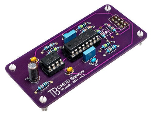
"CMOS Steezer" from TB Audio: Available from from the store From the mad genius who packed the Roland Dimension D Chorus and API 550A EQ into 500-series kits comes a hi-fi fuzz Colour based on the unique CMOS inverter topology. More info, kits, and sound samples available at the DIYRE Store.
"TM79" from Eisen Audio: Available from the store Eisen Audio, whose credits include designs for Purple Audio, AwTAC, and NonLinearAudio, is one of the premier design firms working in analog pro audio. Their contribution to the Colour format is a multi-stage saturator packed with 70's console-and-tape sound. Kits, sound samples, and some wonderful notes from the designer are available at the DIYRE Store. TM79 Colour Kit - $54.95 "Colourupter" from XQP Audio: In development XQP is currently working on converting their awesome "545 Optical Disrupter" into a Colour module. You can learn more about the Disrupter at XQP's website. 
??? from Louder Than Liftoff: Coming soon Louder Than Liftoff has been working behind the scenes on not one but three Colours all to be released at the same time. LTL has not revealed any details about their Colours yet but... is that a real tube I see at the bottom of this page? Exciting stuff! We invite you to get in on the fun by building your own Colour 500-Series Palette kit. PS. Are you working on your own Colour design? Check out the Designer's Toolkit and drop us a line to discuss your idea.
Colour Production Pt. 1: Parts Begin to Arrive March 5, 2014 15:08 3 Comments


Colour Design Pt. 6: Pricing and Pre-Order December 12, 2013 13:22 5 Comments
The Colour Products We're Launching
The initial Colour launch will include four products: the 500-series Palette and three "primary colours." While we've prototyped many more than three colours in the last year-and-a-half, we've decided to release only what we consider to be the three strongest and most distinct at the moment. These are:- CTX imparts vintage transformer saturation in the best way possible, with a real chunk of Cinemag iron. A bass "tilt" emphasizes the transformer's low-frequency harmonics.
- JFT generates crispy, triode-ish saturation from a gently overdriven JFET transistor.
- 15IPS is a germanium diode-based, soft clipping circuit that simulates the natural compression of analog tape. A subtle, resonant, high-pass filter replicates the low-end response of certain tape running at 15 inches/second.
- Eisen Audio
- Louder Than Liftoff
- TB Audio
- Abe Chapman of AC Sound
- Big Bear Audio
- Nathan Bowers of THD Industries
- Dane Tate of XQP Audio
- Bearcat Audio
Setting a Price
From the very beginning, it's been our goal to make Colour as affordable as possible. With a successful Kickstarter campaign, we'll be able to offer kits and assembled units for a truly game-changing price. Before we get to the numbers, let's talk about how we achieved Colour's price point. We did not do it by cutting corners on components or hardware. All of the electronic components are top of-the-line and sourced from reliable US distributors (no chance of counterfeits). The ICs are state-of-the art chips from from THAT Corp and TI, transformer is from Cinemag, capacitors are from Nichicon, switches are from Alps, connectors are from Samtec, and potentiometers are conductive plastic-type from BI Technologies. The Palette PCB is protected by a piece of 19-gauge, zinc-plated steel. The 500-series blackplane connector is gold plated. In short, Colour is manufactured to a higher standard than many 500-series modules that sell for $500+. We achieved our price point through a combination of bulk pricing, prototyping cheaply, and creative design thinking. Attractive pricing and small-batch manufacturing rarely go together. For an illustrative example, see the pricing schedule for the LME49710 opamp we are using (direct link). Manufacturers ordering in quantities of less than 100 pay twice as much per chip than manufacturers that can order 1000+ at a time. Similarly, PCB and hardware manufacturers charge hefty setup fees and then relatively little per unit. It may cost $100 to make one PCB and only $1,000 to make 1,000. We're overcoming this obstacle by launching withwith one big order via Kickstarter. If the Kickstarer is successful, we'll be able to place orders with the big boys and price accordingly.
Although it lasted more than a year, the Colour design process was surprisingly inexpensive, under $5,000. We were able to do this primarly by 1) not paying ourselves up front and 2) making our prototypes in house. #1 is part of the nature of being a lean, unfunded, hardware startup, and it's a "luxury" companies with salaried staff cannot afford. As much as I hope personally never to work 18 months on spec again, at the end of the day it is one less major expense to recoup.
#2 is a unique benefit of working out of a co-operative prototyping space (NextFab Studio in Philadelphia, PA). We spent a total of $0 on mechanical prototyping services, and etched PCBs for rough prototypes ourselves. Overall, we avoided thousands of dollars in design costs that would have otherwise been built into the price.
We designed Colour from the ground up with cost in mind. Where only the best component would do, that's what we used. Where the most expensive component did not present a significant performance gain, we shopped around and evaluated numerous options to find the best combination of performance and price. For example, we built full, working prototypes with five different potentiometers before making our final choice. By optimizing component choices in this way, we've reduced parts cost by a third since our first prototype without sacrificing an ounce of performance.
Finally, we're simply not charging as much as we could (some would say ought to). It's a common rule of thumb when pricing DIY kits to charge a bit more than it would cost for customers to source all of the parts themselves. We're charging significantly less. We're keeping our prices and margins low because our top priority is getting Colour in the hands of as many engineers, DIYers, and designers as possible. We're also betting that most users will want more than one Colour.
Enough build up, what's the price already!? Pending the success of our Kickstarter campaign, we'll be offering Palette kits for $119 and full Colour kits with the three primary colours for $249. For the Kickstarter, however, we're going to go even lower to reward early adopters and to test the sustainability of those prices:
- $95 for Palette kit
- $175 for full Colour kit (Palette + 3 colours)
- $299 for Colour assembled and tested
Colour Design Pt. 5: Finalizing the Colour Module Format November 14, 2013 13:55 3 Comments
 Demonstrating how Colour works for the upcoming Kickstarter video. Photo by Zach Robbin.
Colour as a Platform
There are four parts to a complete Colour unit: the Palette (motherboard) and three Colours (modules). The palette provides all of the power, I/O, control, and gain/attenuation circuitry to the colours, which provide the, well, color. (As an American, I spell 'color' with five letters. Co-designer Link Simpson is Canadian, hence the 'u'.) And while we're releasing three colours of our own with the palette, Colour is intended to be first and foremost a platform for the community to experiment with analog saturation circuits. Therefore, defining the specifics of the modular format was one of the most important and labored-over design decisions in the project. My design goals were for the colours to:- have as much vertical clearance as possible for large components;
- make a solid mechanical connection with the palette;
- make a solid electrical connection with the palette;
- mount/dismount quickly and easily;
- be protected against being inserted backwards.
To address the first concern, I opted for 1/8" standoffs, so that the mounting surface for components on the colours was only 3/16" higher than the palette. This leaves .968" of clearance for colour components within the allowed 1.5" 500-series space, enough room for large caps and small transformers.

When I turned to choosing standoffs, I realized that design goals 2 and 3 stand in opposition to each other: in most cases, the sturdier the connector, the more time and work it takes to fasten and unfasten. After ordering and demoing several different snap- and screw-in standoffs, the one I found that married sturdiness and convenience most happily was the Keystone 9018 (pictured). The 9018 spacers allow the colours to be simply pressed in, instead of screwed, and the locking nylon tabs ensure the colour cannot be removed without squeezing the tabs together.
Electrical Connectors
Finding the perfect electronic connector involved negotiating between another set of contradictory design goals: 1 and 3. By reducing the space between the colours and the palette to make room for big components on top of the colours, I had given away the space I needed below for the .100" pins and headers I had previously chosen for the electrical connectors. My first attempt at a solution was to remove the connectors altogether and place pads on the PCBs of the palette and colours themselves that would mate when the colours were screwed down. This would eliminate the need for spacers as well, since the colours could mount on the same standoffs as the palette PCB. And it would buy an extra 1/8" of clearance for the colour components!
The ill fated spacer- and connector-less colour mounting approach.[/caption] Unfortunately, it proved impracticable for a couple of reasons. First, it required large regions of the palette PCB to be routed out to provide clearance for the bottom of the colour PCBs. This compromised the structural integrity of the palette board and made wiring and grounding more risky. Second, the PCB pads simply did not mate very well. The connections between some pads were intermittent, depending on how thick the plating was on adjacent pads. So it was back to the now-familiar process of catalog digging, sample ordering, evaluating, and repeating. Except this time the process was almost a pleasure, since it turns out there is a company called Samtec kicking the connector industry's ass from here to next Tuesday. Samtec is the only electronics manufacturer or distributor I've come across with a truly functional, 21st-century website that makes it easy to find, sample, and buy their components. And they happen to make a .100" header sits on top of the PCB and mates with pins from below. Brilliant! Problem solved. (Note to other US/European manufacturers: give me a functioning website, phone support, and free samples and I will give you my money!)
The final colour mounting solution, with Keystone spacers and Samtec .100" connectors.[/caption] Finally, to meet design goal 5, I've offset the front row of electrical connectors so that the colours can only be inserted into the palette in one direction. This protects the colours from being destroyed by plugging the audio inputs into the power output connectors. This small revision will be implemented in the final PCB.
Making Your Own Colour
If you're interested in developing your own colour, or just playing around with the format, bookmark the Colour Module Design Guide. The design guide will host PCB templates and self-etch files, and pre-made colour proto-boards will be available soon. Thanks, as always, for following along and please do stay tuned for the next post in which I'll discuss the kit ordering options and, of course, the price!Colour Design Pt. 4: Big Time Interface and Circuit Overhaul August 9, 2013 17:40 16 Comments
In summary, after doing some mixes with the most recent prototype pictured below, I became dissatisfied with the current approach of feeding the dry signal to the colours in parallel and controlling how much of each is mixed in with the dry signal. I found that in almost every application, I was keeping the colours cranked all the way up and turning the dry signal all the way down. In retrospect, this makes sense, as the colours themselves are tuned to impart only subtle distortion, the way a colored preamp or compressor might.

The most recent physical prototype (#4) with JFET, tape, and Cinemag colours installed.[/caption] So I went back to the drawing board, this time with some real mixing experience in hand. One of the first things I knew I wanted to do was simplify the interface. While the idea of having control over the amount of each colour is tempting on paper, in practice I found that I didn't want to be bothered. What I did find myself doing was turning individual colours up and down quickly to hear what the signal sounded like with them bypassed. So I decided to substitute the individual colour volume controls for simple in/out switches. This interface trades a little control for a lot of ease and simplicity. This jives with my original intuitions about Colour: that, like a preamp or tape machine, a harmonics generator is not a piece of gear people want to spend significant time tweaking. Rather, it's something that we should be able to switch into the signal chain with a press of a button, nod with satisfaction, and move on.

A mockup of the current interface with bypass switches instead of individual volume controls for each colour.[/caption] I've also reworked the circuit from the ground up, putting the colours in series rather than parallel and adding a master input drive control. This approach is taken directly from real-word recording practice. When a microphone signal travels through a preamp, and compressor to a tape machine, the coloration from those devices is not applied in parallel. Rather the harmonics generated by the preamp are modified by the compressor, which are then further tempered by the tape. Indeed, part of the art of being a tracking engineer is combining complementary pieces of gear into a signal path. Putting the modules in series makes Colour sound and behave more like a true recording chain.
The new working schematic , with colour modules placed in series with a single input drive control.[/caption] So, that's where are as of now. Circuit boards are already on order for the new design outlined above. If all goes well with this round of prototyping, hopefully I'll have a kit to offer very soon. As always, I welcome and appreciate your thoughts on this project. It's come as far as it has in no small part thanks to your feedback!
The "Colour" Project Pt. 3: Prototyping the Motherboard December 7, 2012 17:39 20 Comments
Making the Color Modules Larger
Our primary aim in making the distortion stages modular is to make "Colour" into an open platform for design and experimentation. With this in mind, we realized that we should make the modules as large as possible for more complex circuits and bigger toys like large caps, transformers, and optical cells. In order to make the modules bigger, however, we need to make some room on the motherboard. Most of the following revisions will probably make their way onto the 0.2 PCB:- Using DIP8 rectifiers instead of discrete diodes
- Changing mounting holes from #6 to #4 drill size
- Removing some of the test points
- Placing some low-profile components under the modules (.25" clearance)
- Using 16-pin IDC connectors rather than MTA for the stereo link
Standardizing the Connectors

Because we are opening up the color modules to third-party developers, it's essential that we specify a standard, off-the-shelf connector for mating the modules with the motherboard. We settled on 6-pin, single row, 0.1" (2.54mm) pitch pins and headers.These are the same used to plug Arduino "shields" into the motherboard and are available cheaply from countless parts distributors.

Arduino shield connected to motherboard
Rethinking the Interface
Since the concept phase, we've heard a lot of feedback, floated a lot of ideas, and even had some mildly heated debates about which controls to include on the front panel. The various controls we've at one point considered including are:- Input gain (master or for each module)
- Output trim
- Wet/dry mix for each module
- Bypass (master or for each module)
- Master bypass
- Three wet/dry mix controls (one for each module)
- Master output trim
- Master bypass switch
- "Saturation" Input drive switch
- Three module volume controls
- Dry signal volume
- Output trim
Dropping the "U"?"
Our working title seems to have some staying power. Nothing else we've thought of communicates the intent and use of the unit quite as succinctly as "Colour." But I just can't get used to typing that extra vowel. And even Link, whose Canadian tendencies inspired my choice for the British spelling, prefers the "more efficient" American spelling. I'm currently leaning towards dropping the 'u', but let me know in the comments if you have a strong (or even mild) preference.What's next?
The revisions we've looked at today all have to do with the motherboard. Next time we'll get into the actual "colors" with schematics and sound samples documenting our revision process for the modules. Thanks for following along while we slog through the gritty details!The "Colour" Project Pt. 2: Going Modular August 31, 2012 16:48 10 Comments
Then came the big "aha!" moment: we decided to make the distortion stages socketed, and therefore interchangeable.
The new design splits the circuit up into a motherboard, which provides the input, output, and control circuitry, and three daughter boards, which contain the various colors (distortion stages). This changes everything. The "Colour" we're designing now is not so much a single piece of gear as a platform for experimentation and discovery. The user will now have the option to choose which colors to include in her palette and, this being DIY after all, the ability to create her own. And the DIY community will have the opportunity to design and release their own "colours." In fact, there's reason these "colours" should be limited to distortion--almost any type of signal processing could be made into a module!
Next Week: The colours we're working on
Now that we've covered the motherboard in depth, we can jump into the sexy stuff next week when I'll detail the distortion stages Link is working on. In the meantime we'd like your help brainstorming a Wish List of signal processing modules you'd like to see. No idea is too crazy!
Many thanks to everyone who has expressed their enthusiasm for this project.
Designing a New Piece of Recording Gear Pt. 1: The Concept August 7, 2012 14:22 60 Comments
For a while, I had been on the lookout for a collaborator to work with to bring something utterly new to the DIY community. Someone with professional design chops who understood the DIY community and was open to the idea of making their designs open source. I was lucky enough to find Link Simpson by stumbling accross his Steller Studios DIY projects page. Expecting to find the usual gallery of completed kits and and guitar pedals, I found instead totally new designs for a preamp, compressor, personal headphone mixer, and more, all made from the ground up by Link himself. This was some next-level stuff! So I arranged a call and we began immediately throwing around project ideas.
What should we make?
I went into the brainstorming session with three main criteria for our new piece of audio gear:- Must be inexpensive, safe, and easy to build. Only modern, off-the-shelf components. No tubes or high voltages, avoiding AC power completely if possible. I wanted this project to be as newbie-friendly as possible.
- Not another clone, preamp, or compressor. I have only admiration and respect for the people who have brought great vintage clones to the DIY community, but that's not the direction I wanted to go with this project. Similarly, I don't think there will ever be a day when we have too many preamps or compressors (will there ever be too many craft beers? ice cream flavors?), but I wanted to do something more off-the-beaten-path.
- Something sexy. I'd had a lot of fun developing a passive summing kit and reamp box, but they weren't the kind of projects people were likely to drool over. I wanted our project to be something that would really capture peoples' imaginations and inspire them in the studio.
For a couple of weeks we tossed a ton of ideas back and forth, until Link astutely pointed out that most of my ideas included "the ability to push it hard for harmonic saturation." Why not--Link proposed--just focus on the harmonic saturation? Bingo.
"Harmonic distortion is sonic varnish." -Allen Farmelo
The Vision

Refining the Design
Now that we had our core idea, we faced another round of big decisions. "Which types of distortion?" "How should it be racked and powered?" "How should we balanced the output?" Etc... For today, I'll cover our current thinking in regards to the distortion types and powering/racking the unit.
Distortion Types
Link proposed a few different distortion stages:
- JFET, tube-like distortion
- Rectified, octaver-type
- Enhancer-type effect with treble-focused distortion
- Opamp/diode tape-like distortion
All of these would be achieved with sold-state, currently available parts, similar to the distortion stages in gear like the Empirical Labs Distressor or the Crane Song HEDD. One thing we agreed upon early on is that our goal with this unit would not be to emulate some "classic" sounds, such as "tape" or "triode," but to create sounds that we found beautiful or exciting. This is in line with our shared belief that words like 'tape' and 'tube' have been abused into meaninglessness by marketing departments.
Powering and Racking
As we weighed power supply options and priced out a run of metalwork, it became clear that developing an API 500-series module would allow us to focus more deeply on the audio circuit itself and make the unit affordable enough to mass produce. Indeed, the more experience I have with designing and dissecting audio gear, the more I come to the conclusion that modular formats such as the API 500-series and the 51x Alliance provide the best solution for most rack-mount gear. This is especially true for small manufacturers (DIYers being the smallest) who don't move enough volume to get bulk discounts on specialized components such as the power supply tranformer and metalwork. This is something that the DIY synth world has been onto for years and that, thankfully, is finally gaining ground in the recording community. I am, however, very reluctant to alienate those builders who don't have a 500-series rack, and I know how frustrating it is to see great gear released in a format you're not ready to commit to. So the final version of the PCB will certainly have a built-in option for racking the unit in a 1RU case.
What's Next?
In the next post, we'll delve deeper into the technical details of the circuit and pose some more specific questions about how the unit will operate. For now, we'd love to get your feedback on the core idea and features. Can you see yourself using something like this? Are there any important features you think we've overlooked? What do you think of the idea of ditching words like 'tape' and 'triode'?