Colour for Beginners: Design Your Own High-Pass Filter January 15, 2015 16:31 4 Comments
Hi, my name is Chris. I’m a musician, I like origami, and I’ve been working here at DIYRE for 5 months (Peterson still won’t tell me what the letters stand for). So since I've been putting so many of these "Design Your Own Colour" boards in the Colour Palette kits, I’ve decided it’s about time I got my hands dirty with actually Designing My Own Colours.
Designing Your Own Colours (Without Any Electronics Knowledge)

We have so many of those little white rectangles lying around, and before I knew what they were I had come up with plenty of alternative uses for them (coasters, Tarot Cards, etc). Then, one day, out of the blue, when Peterson caught me using them as banquet tables for a model of the QE2 I was constructing, he mentioned in passing that they could be used to design and prototype your own custom Colours. I said, “Thanks, no thanks,” and finished my model. That’s when, all of a sudden, months later, it hit me: I could use these to design my own Colours!
Since I'm not an Electrical Engineer, and I really don't know what I'm doing, I wanted to start with something as simple as possible. I tried to think of what would be a useful circuit to have in the studio, and I came up with high-pass, and low-pass filters. I asked Peterson for suggestions as to what he thought might be a nice simple filter design to adapt for my first circuit, and he kept trying to tell me about some sort of Salad he’d been eating the other day, and something about having lost his keys—he’s always doing that— so no help there. Thanks for nothing, Peterson. Anyway, I settled on a Sallen-Key high-pass filter to be my first attempt.
High-pass filters can be used for lots of things. Things like eliminating mic stand rumbles, cleaning up vocals, or making distorted guitars layer nicely. The fact that they have so many uses makes them… well, useful. I also wanted an active filter so that it accounted for the drop in gain from the filtering part. Also, it’s a second-order filter for those of you who are into that sort of thing. I think that has to do with how intense the dropoff in amplitude is above or, in this case, below cutoff frequency. The higher the order, the steeper the slope at the cutoff. All right! Sallen-Key it is!
The Filter Circuit
This is the Sallen-Key Circuit. The resistors and capacitors are the filtering jazz, and the op-amp applies the gain. This is undoubtedly an oversimplification, but the nice thing about physics is they work whether you understand them or not. Using this imperfect knowledge and this online Sallen-Key calculator you can mess with your values and tinker with what exactly the frequency response of your circuit is. Another neat thing about this circuit is that if you switch the positions of the Rs and Cs, the circuit becomes a low-pass filter. I’ve seen 80hz high-pass filters on some random pieces of gear I have in my room so I figured that was a nice, safe, and functional target to aim for. The calculator I linked to has a mode where you can put in your desired cutoff frequency and just the capacitor values and then it will spit out the resistors you need. So, doing just that I put in 80hz and 0.1uf for both capacitors, and it spit out 20k for the resistors. Lovely! Now we are cooking.
If you wanna build this exact filter these are the parts I used:
| Component | Value | Circuit Position | Quantity |
|---|---|---|---|
| Resistor | 20k | R1, R2 | 2 |
| Capacitor (film) | 0.1uf | C1, C2 | 2 |
| Capacitor (ceramic) | 0.1uf | TBA(To Be Announced) | 2 |
| Single Op-amp (TL071CP) | N/A | IC1 | 1 |
| 8-pin header | N/A | CON1 | 1 |
Putting the Circuit on a Colour
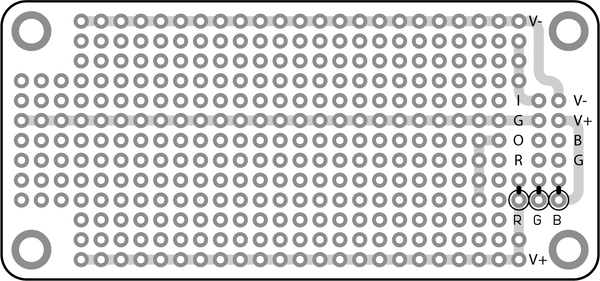
So the Colour Protoboard is laid out with an Input Bus(I), Output Bus(O), your split DC power supplies V+ and V-, and your Ground down the center of the board. The RGB connections are so you can set the color of the LED on the face of the Palette for your effect. This is something I didn’t feel like messing with this first go around, because these resistors have nothing to do with the signal processing. One little trick to these boards is a sort of breadboard typo that got in there; the Output bus isn’t actually connected to the Output connector. You will have to throw a piece of wire from the Bus to the Output Pin. I used the extra lead from one of my resistors.

The orange bubbles on the far left are capacitors (ceramic, 0.1uf) which don't show up in the schematic. I'll get to what they do in a second, but, strictly speaking, they aren't a part of the Sallen-Key circuit.
In laying out my board I decided to keep things sort of separated from each other so that I could keep track of what I was doing. I put the op-amp right in the center and the caps and resistors by the input bus. Those two yellow things on the far left between the DC and ground are capacitors. Peterson had me throw them in to prevent noise on the power line from getting into the circuit. It actually works on the same filtering principle as the other parts of the circuit. Capacitors are strange. They have lower impedance at higher frequency and high impedance at low frequencies. They also don’t pass DC (which I suppose could be thought of as No Frequency (which rhymes with low frequency)). The noise is all high-frequency interference so those capacitors give it an easy path to ground, and don’t let it affect the op-amp.
In soldering mine together, I put a lot of connections on the underside of the board, but if you are doing that you have to keep them really flat otherwise your board won’t fit into the Palette correctly.
Here are some pictures of my finished board:


Using Our New Colour
After I was done, I plugged mine into the Palette and ran some signal through it. The first time I plugged mine in I had used 100k resistors which, honest to god, resulted in the lamest filter ever with the stupidly boring cutoff of 15 hz, which is virtually inaudible. I was happy the circuit worked-- and I did test that there was a volume drop below 15 hz-- but I wanted something more exciting. So I lowered the value of R1 to 10 ohms. This bumped the cutoff frequency to 1.5 khz and, for some reason, put a huge peak of amplification right at the cutoff. It sounded pretty sick so I called it a night.
Using the little Breadboards was way easier than I thought and I feel like I learned a lot. I’m still fuzzy on how exactly the whole of the filtering part adds up, along with how the op-amp, as a result of the filtering, is applying gain. I’m sure, in time, I will feel more comfortable with all of that. Overall this was a great experience, and it felt pretty great to have built my own analog signal processor. Using the Colour Palette really seems to take a bunch of the hassle out of the whole affair. So if you purchased a Colour Palette and have some of these breadboards around, I hope this post will have demonstrated that it’s really pretty easy to make your own highly-useful circuit for your Palette.
What's Next?
I’m excited to make more things! I haven’t decided what I’m doing for next month but I’m open to suggestions. If you have any questions or corrections, feel free to leave a comment.
Comments
Frans Stummer on March 16, 2015 15:59
Allright, here is where it gets sick and perverted. Like, use stuff for things they never were intended to. Don’t stop here – twist it. Somebody someday had to say it, it’s today and it’s me: build a clean little gain block for the Color. Why? Isn’t that the most insane stupid thing somebody could do with the Color? Well, yeah, like, exactly. It would be good for two things – one, you could run into the first module like your input pot intended… then, second stage a little gain. To drive the third stage a little harder. Okay. Booooring. So here number two, this is the good one. Pervert the Color as a low-gain mic preamp for high output tube mics or dynamic mics on very loud sources. Run your U47 (or whatever has thou) into stage one (which never needs the stupid 40dB gain your showy hipster preamps have as a starting point) with, hmm..hmmm.. 15 or 20 or 25 dB of gain. BAM! Still two stages to go, or leave them out. Why waste a preamp that goes from 35-70dB with a signal that screams (ever recorded drums..?) when you have to pad it down anyway? Kinda like driving that Porsche with the handbrake fully on. Admit it, it’s such a sickly sweet idea. I don’t mean the car, stupid.
Brad McGowan on January 16, 2015 19:32
Be sure to place your 0.1uF ceramic bypass caps (the yellow ones) right at the power pins of the op amp for best performance and stability. Also you could try exploring different op amps for cleaner sound and lower noise performance. My personal favorite is the LME49710.
Johnny on January 16, 2015 15:08
Keep it up!
Kevin on January 15, 2015 16:57
Very entertaining, Chris! Thanks for sharing. Hope to hear you on the podcast again soon.
Comments are closed for this post.